
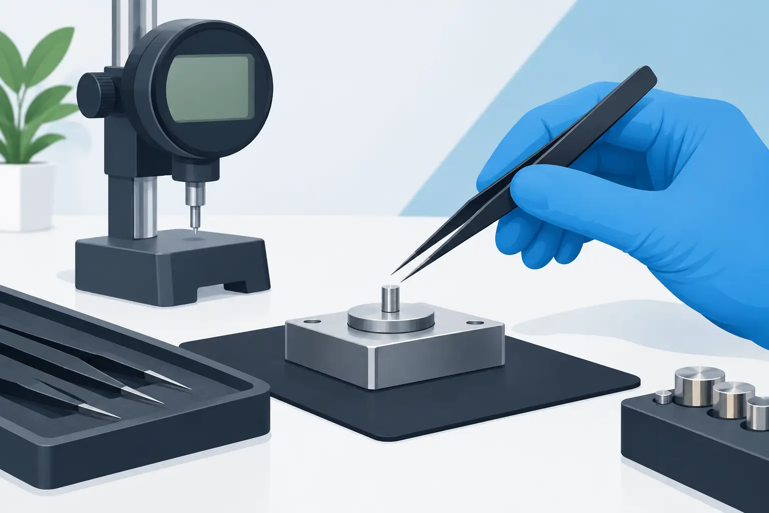
A 0402 capacitor that appears to have the wrong value is not always a bad component. Residue on the tips, a drifting contact position, or an uncompensated fixture can add enough parasitic resistance or capacitance to mislead the measurement. Knowing how to calibrate test tweezers correctly helps separate instrument error from a real component fault before a repair decision, incoming inspection result, or rework action is made.
For tweezer-style LCR instruments, calibration is often used to describe two related but different processes: user-performed open/short compensation and formal metrological calibration. The first corrects for the electrical effects of the probe tips and measurement geometry. The second verifies that the instrument meets its published accuracy specification against traceable standards. They serve different purposes, and treating one as a substitute for the other creates avoidable uncertainty.
Start by Identifying the Calibration You Need
Open/short compensation is the routine adjustment most users can perform at the bench. It establishes the measurement baseline for the tips, fixture, or Kelvin probe connection currently in use. The instrument measures an open condition to characterize stray capacitance and a short condition to characterize residual resistance and inductance. It then subtracts or compensates for those effects during subsequent measurements.
Formal calibration is a controlled comparison of the instrument against known standards, typically performed with documented procedures, suitable environmental controls, and traceable reference equipment. This process may result in a calibration certificate and is appropriate when a quality system, customer requirement, or internal measurement-control program requires documented accuracy.
Use open/short compensation whenever you change tips, attach an accessory, notice unstable low-value readings, or begin precision work after the instrument has been stored or transported. Seek formal calibration at the interval specified by the manufacturer, after repair or suspected damage, or when your work requires traceability.
Prepare the Tweezers and Work Area
Compensation is only as good as the physical condition of the measuring path. Inspect both tips under magnification before beginning. They should be clean, aligned, free of oxide, and able to close with consistent contact pressure. A small film of flux residue can be significant when measuring low resistance, ESR, or small capacitance values.
Clean the tips using a method approved for the instrument. In most cases, a lint-free swab lightly moistened with high-purity isopropyl alcohol is suitable. Do not scrape plated tips with abrasive material or bend them to force alignment. If tips are worn, loose, damaged, or unable to close evenly, replace or service them before compensating. Calibration cannot correct a mechanically unreliable contact.
Allow the instrument to stabilize at the working temperature. A meter moved from a cold vehicle, hot production area, or direct sunlight should sit at room conditions until its reading behavior is stable. Avoid performing compensation next to switching power supplies, high-current conductors, RF transmitters, or strong electrostatic sources. These conditions may not prevent calibration, but they can make repeatability worse.
Before starting, confirm battery condition and use the measurement mode, frequency, and accessory configuration intended for the job. On advanced instruments with selectable test parameters, compensation may be tied to the active setup. A calibration performed at one frequency or with one adapter should not automatically be assumed valid for another.
How to Calibrate Test Tweezers With Open/Short Compensation
The exact menu names, prompts, and storage behavior vary by model. Follow the operating instructions for the specific meter, but the physical sequence is consistent.
Perform the open measurement
Power on the meter and select its calibration or compensation function. Hold the test tips apart in free air, with no component, conductive surface, fingers, or bench mat close to the tip ends. Keep the opening position similar to the spacing used during normal measurement, particularly when the instrument measures very small capacitance values.
Start the open step and keep the tweezers still until the instrument confirms completion. This measurement characterizes the parasitic capacitance and leakage present in the open tip geometry. Do not hold the metal portions of the tips during this step. Your body can introduce a measurable capacitance path.
Perform the short measurement
For the short step, use the manufacturer-supplied shorting fixture or the specified calibration fixture whenever available. A dedicated fixture provides repeatable, low-resistance contact and is preferable to simply pinching the tips together by hand.
Close the tips on the shorting standard using normal, repeatable pressure. Ensure both tips contact the intended conductive surfaces squarely. Initiate the short measurement and wait for the completion indication. The meter records the residual impedance of the closed measurement path.
If a fixture is not available and the manual permits direct tip-to-tip shorting, clean the tips first and use a consistent closing position. This is acceptable for routine field work, but it is less repeatable than a proper fixture and can be insufficient for critical low-ohm or low-ESR verification.
Confirm that the correction was stored
Some instruments retain compensation after power cycling, while others apply it only to the current session or active range. Confirm the status indicator, prompt, or settings screen after the routine completes. If the meter reports a failed calibration, do not repeat the command blindly. Inspect tip cleanliness, alignment, battery state, fixture contact, and the selected configuration first.
Repeated failures with a clean fixture may indicate damaged tips, an internal connection problem, or an incorrect calibration method for that model. At that point, service evaluation is more useful than forcing a result that looks acceptable but is not repeatable.
Verify the Result With Known Components
Compensation is not complete until it is checked against known values. Select stable reference components appropriate for the ranges you use most often. A precision resistor is useful for resistance and ESR-related checks, while a low-loss capacitor and a known inductor can expose issues in capacitance or inductance measurement.
Measure each reference several times, removing and repositioning it between readings. The displayed value should be consistent and within the accuracy limits for the instrument, test frequency, and component type. Compare against the component’s tolerance, not just its marked nominal value. A 1% resistor and a 20% ceramic capacitor do not provide the same quality of verification.
| Check condition | What it can reveal | | — | — | | Open tips in free air | Excess offset, contamination, or nearby capacitance coupling | | Shorting fixture | Residual resistance, poor tip contact, or unstable closure | | Precision resistor | Resistance accuracy and contact repeatability | | Stable capacitor | Capacitance offset and effects of test frequency | | Known inductor | Inductance behavior and lead or fixture influence |
For very small SMD components, the component itself may be close to the instrument’s practical resolution limit. At that point, placement, contact pressure, dielectric behavior, and test conditions matter as much as the nominal component value. The correct question is not whether every reading matches a label perfectly, but whether repeated measurements are stable and within the stated uncertainty for the setup.
Common Calibration Errors That Produce Bad Readings
The most common error is compensating with dirty tips and then cleaning them afterward. Cleaning changes the contact condition, so perform maintenance first and compensate second. Another frequent problem is using a short made from a random wire, solder blob, or worn pair of tweezers. Its resistance and inductance may be larger than expected, especially at higher test frequencies.
Users also sometimes compensate in a different physical configuration than the one used for measurement. If a Kelvin probe connector, extended tip, or fixture is added after compensation, the stored correction no longer represents the full measurement path. Re-run the procedure with the accessory installed.
Do not expect open/short compensation to correct component-specific effects. A multilayer ceramic capacitor can shift with DC bias, temperature, frequency, and mechanical stress. An inductor may change value when measured near ferrous tools or energized circuitry. ESR readings depend on the selected test frequency. These are characteristics of the device under test and measurement conditions, not necessarily a calibration failure.
When Bench Compensation Is Not Enough
A successful open/short routine establishes a reliable working baseline, but it does not prove traceability or guarantee that every range meets specification. Formal calibration is the right next step when measurement records support production acceptance, regulated work, contractual quality requirements, or a documented calibration schedule.
It is also warranted after a drop, liquid exposure, tip assembly replacement, repair, or persistent disagreement with stable reference standards. A professional calibration service can test the meter across relevant ranges and conditions rather than relying on a single spot check. For users of LCR-Reader instruments, retain the service record with the meter’s serial number and verify the applicable calibration interval for the specific model and operating environment.
A clean, repeatable compensation routine takes only a few minutes, yet it protects the measurements that determine whether an SMT part is accepted, replaced, or blamed for a fault. Treat the fixture, tip condition, and verification components as part of the measurement system, not as accessories to the meter. That approach produces readings you can act on with confidence.