
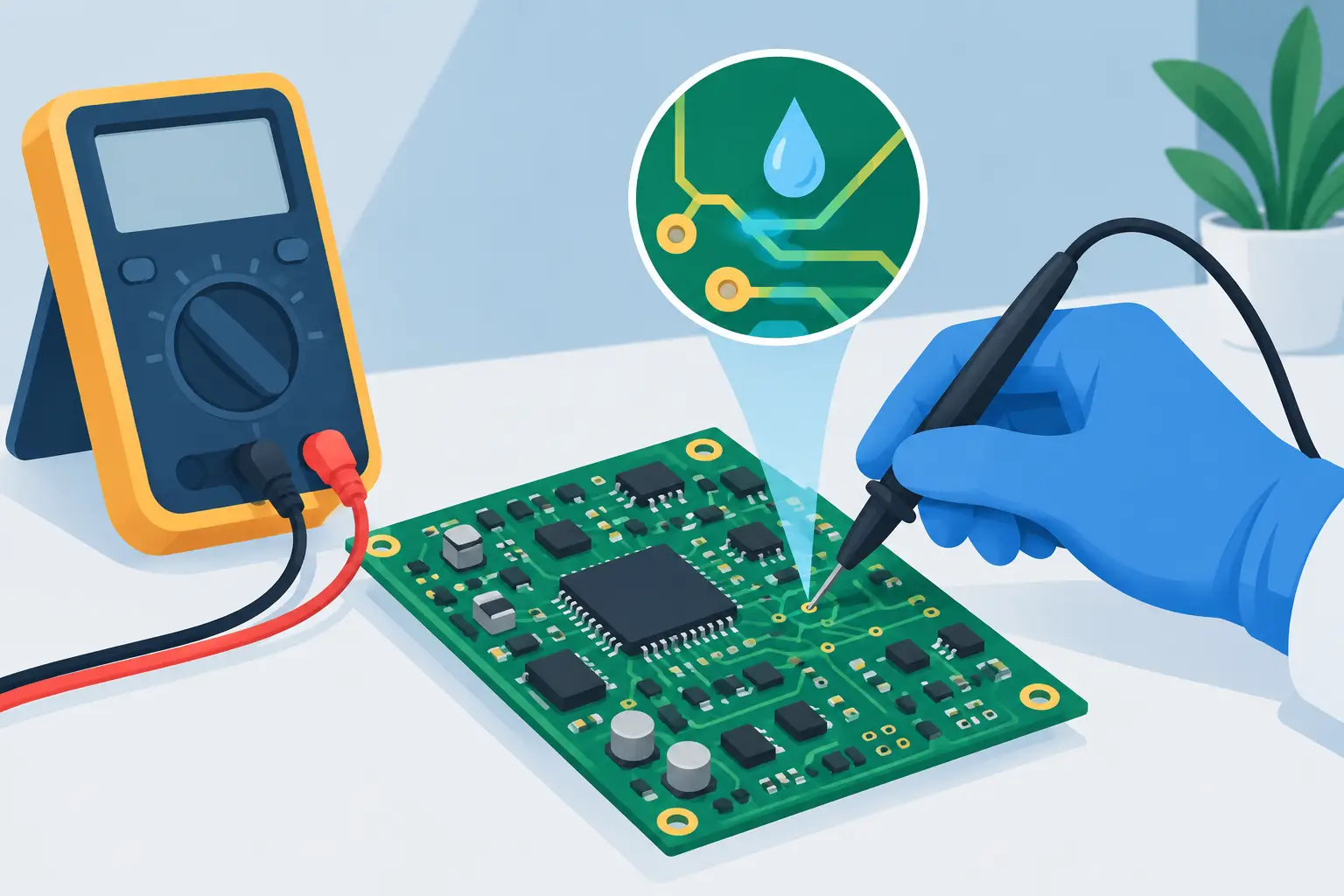
A board that draws 80 mA when it should draw 2 mA is not necessarily shorted. It may have a partially conductive ceramic capacitor, a damaged protection diode, contamination under a fine-pitch IC, or an IC held in an unintended operating state. Effective PCB leakage diagnosis starts by treating the excess current as evidence, then narrowing its path with controlled measurements rather than replacing parts at random.
Leakage faults are often intermittent, temperature-sensitive, and difficult to see. They may allow a product to boot, drain its battery overnight, fail a standby-current specification, or become unstable only after humidity exposure. The most efficient workflow separates a true leakage path from normal circuit consumption, identifies the affected rail, and verifies each suspect component before removal.
Define the leakage before testing
Start with the schematic, board power tree, and expected current consumption for the operating condition being tested. A current reading without context is not a diagnosis. Many boards have brief startup surges, active radio bursts, charging circuits, memory-retention currents, and regulator quiescent current that can be mistaken for leakage.
Measure the board from a current-limited bench supply at its specified input voltage. Record the current in at least two states: power-off or standby, if applicable, and normal operation. If the board uses a battery, test both at the battery terminals and at the regulated rails. A fault before the charger or protection FETs can look very different from a fault on the main system rail.
A useful first distinction is between a hard short and leakage. A hard short typically produces very low resistance to ground and reaches the supply current limit quickly. Leakage is more likely to show a measurable but not near-zero resistance, or a current draw that changes with applied voltage, temperature, humidity, or board state. Do not rely on resistance alone, however. Semiconductor junctions, input capacitors, and parallel loads can make a healthy rail appear low resistance on a handheld meter.
PCB leakage diagnosis begins with rail isolation
The highest-value step is finding which rail carries the unexpected current. Check each accessible rail against ground with power removed, then compare readings with a known-good board when one is available. The comparison is especially useful on dense products where several ICs and decoupling networks are connected in parallel.
Next, isolate rails methodically. Remove jumpers, open zero-ohm links, lift inductors, or separate load switches where the layout permits. Choose a division point that separates a regulator output from its downstream loads. If the abnormal current disappears when the load side is disconnected, the regulator may be healthy and the fault is downstream. If it remains on the regulator side, investigate the input network, regulator, feedback components, and protection devices.
Avoid cutting traces unless there is no reversible alternative. A lifted inductor or removable link preserves the board and makes confirmation easier. Before applying power to an isolated rail, verify its intended voltage and identify other rails that may backfeed through signal pins, ESD structures, or IC body diodes.
Use controlled voltage injection
When a rail has been isolated, inject a low voltage with a conservative current limit. Begin below the rail’s normal operating voltage, particularly on low-voltage logic rails. Increase only as needed to make the fault observable. The goal is not to force current through the board. It is to supply enough energy for the leakage path to reveal itself without damaging a marginal component.
Monitor voltage and current together. A rail that consumes current at 0.2 V may contain a near-short. A path that becomes significant only as voltage rises may point to a semiconductor junction, transient suppressor, contaminated area, or failing multilayer ceramic capacitor. If the injected current is high enough, use thermal imaging, freeze spray, or a small amount of isopropyl alcohol to locate a warming component. Alcohol evaporation can reveal a warm area, but it is less precise than a thermal camera and must be used with appropriate ventilation and no ignition sources.
Do not interpret the hottest part automatically as the defective part. An IC may heat because it is being back-powered by a failed device elsewhere. Follow the current path and confirm the measurement after isolating the suspected component.
Inspect the common leakage sources
Surface contamination is a frequent cause of standby-current failures, especially after liquid exposure, incomplete flux removal, conformal-coating damage, or high-humidity operation. Inspect closely around battery connectors, power-management ICs, fine-pitch packages, high-impedance analog nodes, and exposed test points. Green or white residue, dendritic growth, corrosion, and darkened laminate deserve attention.
Clean the board using a process appropriate for the contamination and assembly materials, then dry it fully before retesting. Cleaning is a diagnostic action as well as a repair step. If leakage drops substantially after cleaning, inspect for residual corrosion or damaged solder mask that may allow the problem to return.
Capacitors are another common source. A cracked multilayer ceramic capacitor can develop a partial short that varies with flexing, temperature, or voltage. Input and output capacitors near regulators are high-priority checks because they connect directly across power rails. Tantalum and electrolytic capacitors can also exhibit elevated leakage, particularly after aging, reverse polarity, or electrical overstress.
Protection components deserve equal attention. TVS diodes, ESD arrays, reverse-polarity devices, and surge suppressors may fail as a low-resistance or voltage-dependent path to ground after a transient event. Check them in circuit first, but confirm out of circuit if readings are ambiguous. Parallel circuitry can make a good diode appear faulty or hide a leaky one.
Integrated circuits may be the source, but they should not be the first assumption. A damaged USB interface, power-management IC, RF device, or microcontroller can leak internally. More often, however, a passive component on the same rail is easier to isolate and replace. Work from the rail outward before removing a fine-pitch IC.
Measure components without creating false confidence
An LCR measurement is valuable when it answers a specific question: does this capacitor, resistor, or inductor differ materially from the expected value or from identical components elsewhere on the board? Tweezer-style instruments are particularly effective for small SMD parts because they contact component terminations directly and automatically select the appropriate measurement function.
For capacitor troubleshooting, compare capacitance and ESR with a matching component on a known-good board or an equivalent location on the same board. A component that reads open, dramatically low in capacitance, or unusually high in ESR may be defective. Yet a normal LCR reading does not prove that a capacitor has no DC leakage. Leakage can occur only near rated voltage, while LCR meters test with a small AC signal.
This limitation matters. Use an LCR-Reader or similar handheld instrument to identify and compare components quickly, then use a controlled DC source and current measurement to verify suspected leakage under relevant voltage conditions. If the part is connected in parallel with other circuitry, lift one termination or remove it before making a final judgment.
For diodes and transistor junctions, compare forward voltage and reverse behavior in the circuit context. A diode-test result may be influenced by parallel paths, so inspect the schematic before condemning a device. For resistors, confirm that the apparent leakage is not simply a legitimate low-value sense resistor or pull-down network.
Confirm the repair under real conditions
After replacing or cleaning a suspect area, repeat the original current measurement at the same supply voltage and board state. Test more than once. A repair is not verified if the board only passes while cool on the bench but fails after warm-up, flexing, or humidity exposure.
Check startup current, standby current, and functional operation. If the product includes charging, USB, radio, display, or other high-load modes, verify that the repair did not introduce a new issue on a shared rail. For production or recurring repair work, document the measured current before and after repair, the rail involved, the removed component, and any visual evidence. This creates a useful failure history and helps identify design or process trends.
The fastest path through a leakage fault is disciplined isolation: establish expected current, divide the power tree, inject safely, verify components, and retest at the original condition. When each measurement has a clear purpose, even a difficult standby-current problem becomes a manageable circuit path to trace.