
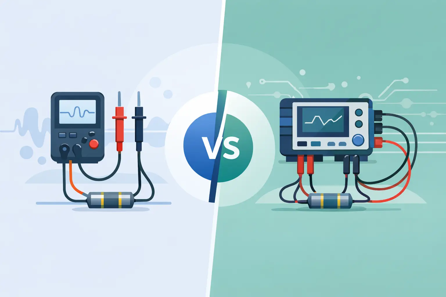
A reading of 0.18 ohms can look like a failed shunt resistor, damaged cable, or poor solder joint. It can also be the resistance of the test leads, probe contact, and oxidized pads rather than the device under test. That is the practical difference behind two wire versus four wire resistance measurement: one method includes unwanted series resistance, while the other is designed to remove it from the result.
For electronics repair, production inspection, and low-resistance verification, selecting the correct method prevents false failures and unnecessary rework. Two-wire measurement is fast and useful across much of the resistance range. Four-wire, also called Kelvin measurement, becomes necessary when the value being measured is close to the resistance of the leads and contacts.
How Two-Wire Resistance Measurement Works
A two-wire measurement uses the same pair of conductors to force test current through the component and measure the resulting voltage. The instrument calculates resistance from Ohm’s law:
R = V / I
This arrangement is simple. A handheld meter, two probes, and direct contact with the component are often all that is required. For general resistor checks, continuity work, cable testing, and many troubleshooting tasks, it is the fastest method available.
The limitation is that the meter sees the entire current path. The displayed value includes the resistance of both test leads, probe tips, contact points, fixture connections, and the component itself. In practical terms:
R measured = R leads + R contacts + R DUT
If a 10 kOhm resistor is measured with leads totaling 0.2 ohms, the added resistance is insignificant. If a 0.05 ohm current-sense resistor is measured with those same leads, 0.2 ohms is a major error. The display may show 0.25 ohms even when the resistor is functioning correctly.
Two-wire readings can also vary with pressure and placement. A sharp probe on a clean copper pad may give a different result than a probe touching solder, nickel plating, or an oxidized terminal. That variation is not always a meter problem. It is often contact resistance changing at the measurement point.
Two Wire Versus Four Wire Resistance: The Kelvin Difference
A four-wire measurement separates current forcing from voltage sensing. Two conductors carry a known test current through the device under test. The other two conductors measure voltage directly at the device terminals.
Because the voltage-sense input draws extremely little current, there is almost no voltage drop in the sense leads. The instrument measures the voltage across the component rather than the voltage across the component plus the force leads and their contacts. The calculation remains R = V / I, but V is now measured at the correct location.
This is why four-wire measurement is commonly called a Kelvin method. It is especially effective for milliohm and low-ohm measurements where lead and contact resistance can exceed the component value.
Consider a 20 milliohm resistor measured with force leads and contacts totaling 160 milliohms. A two-wire method may report approximately 180 milliohms. With properly placed four-wire connections, the voltage sense points are at the resistor terminals, allowing the instrument to report a result close to 20 milliohms.
Four-wire measurement does not make every low reading automatically accurate. The instrument still needs adequate resolution, suitable test current, current-source accuracy, voltage measurement accuracy, and proper calibration. Kelvin connections remove a major error source, but they cannot compensate for a damaged component, contamination at the actual sense point, or a measurement range that is not appropriate for the job.
When Two-Wire Measurement Is Enough
Two-wire testing is usually sufficient when lead resistance is a very small fraction of the expected component value. The acceptable fraction depends on the required tolerance and the consequence of a bad decision.
For example, a 1 percent resistor check at 1 kOhm does not require Kelvin connections. A few tenths of an ohm from ordinary leads will not materially change the pass or fail decision. Likewise, two-wire testing is practical for identifying common resistors on a PCB, checking whether a fuse is open, comparing a suspect circuit path with a known-good board, or verifying switch operation.
Two-wire measurement is also the more convenient choice for compact surface-mount work when the target value is not extremely low. Tweezer-style instruments reduce lead length and make direct contact with chip resistors fast, which helps reduce some of the error introduced by long probe leads. Still, short leads are not the same as a true four-wire measurement.
A useful field practice is to short the test probes together and observe the residual resistance. If the expected device value is much larger than that residual reading, two-wire measurement may be adequate. If the expected value is in the same range, use a Kelvin-capable method or treat the result as an indication rather than a final value.
When Four-Wire Resistance Measurement Is Necessary
Use four-wire measurement when the result must distinguish small changes in a low-resistance path. Typical applications include current-sense resistors, shunts, battery tabs, relay contacts, connectors, cable crimps, motor windings, PCB traces, solder joints, and ground-bond paths.
The need becomes more urgent when specifications are stated in milliohms, when a few milliohms affect power loss, or when the measurement is used for quality-control acceptance. A 10 milliohm increase in a high-current connector may create excessive heating under load even though a conventional continuity test reports a good connection.
Four-wire methods are also valuable when comparing matched parts. In a production environment, a component that reads 4.0 milliohms while comparable assemblies read 1.5 to 1.8 milliohms deserves investigation. A two-wire setup may conceal that difference behind lead and contact variation.
| Measurement situation | Preferred method | Reason | |—|—|—| | 10 kOhm resistor identification | Two-wire | Lead resistance is negligible relative to the DUT | | 100 ohm resistor tolerance check | Two-wire | Fast and generally accurate enough | | 0.1 ohm shunt resistor | Four-wire | Lead resistance can dominate the reading | | PCB trace or solder-joint milliohm check | Four-wire | Contact and probe resistance must be excluded | | Connector and crimp quality inspection | Four-wire | Small resistance increases can indicate defects |
Connection Technique Determines the Result
A four-wire instrument only delivers its intended advantage when the connections are made correctly. The force connections should carry current through the complete device path. The voltage-sense contacts should be placed inside the force contacts, as close as possible to the actual terminals being evaluated.
On a shunt resistor, place the current-force contacts toward the outer ends of the terminals and the sense contacts nearer the resistor body. If all four contacts are stacked on one large solder blob or placed on the same side of a corroded connector, the setup may still include resistance that should have been excluded.
For PCB work, identify whether the goal is to measure the component or the assembled connection. Measuring directly across a resistor body excludes much of the pad and solder resistance. Measuring from one copper land to another may intentionally include the solder joints. Both approaches are valid, but they answer different questions.
Contact cleanliness matters. Flux residue, oxide layers, conformal coating, and light probe pressure can create unstable readings. Use clean contact points and consistent probe placement. Avoid scraping plating unless the test procedure specifically permits it, especially on finished assemblies where surface damage can create a new reliability issue.
Test Current, Self-Heating, and In-Circuit Limits
Low resistance measurement requires enough current to produce a measurable voltage, but higher current can heat the device under test. Since resistance changes with temperature, a reading may drift during a long test or differ from a specification taken at a defined ambient temperature.
This matters with shunts, copper traces, thermally sensitive components, and small SMT parts. A test current that is appropriate for a heavy bus bar may be excessive for a miniature resistor. Check the instrument’s selected range and test conditions when comparing readings to a data sheet or production limit.
In-circuit resistance measurement has another limitation: parallel paths. A resistor measured on a populated board may appear lower than its marked value because other circuitry provides an alternate current path. Four-wire measurement removes lead error, but it does not isolate the component from the circuit. Lift one terminal or use the board schematic when a precise individual value is required.
Selecting a Practical Instrument Setup
The right setup starts with the expected resistance range and required uncertainty. For ordinary component identification, a compact automatic LCR meter with direct tweezer contact can provide a quick, repeatable two-wire reading. For low-ohm verification, use an instrument and Kelvin probe arrangement specified for four-wire resistance measurement.
Review more than the headline resolution. A display capable of showing 0.001 ohms is not automatically accurate to 1 milliohm. Check the stated accuracy, test current, supported resistance range, calibration condition, and connector or fixture requirements. For repeatable quality work, verify the system using known standards and maintain a documented calibration schedule.
LCR-Reader accessories such as Kelvin probe connectors can be useful where a compatible instrument supports four-terminal techniques, particularly when testing low-resistance connections that cannot be reached reliably with standard probes. The key is matching the accessory, instrument capability, and test procedure to the measurement requirement.
Before rejecting a low-ohm component, repeat the test with the question clearly defined: are you measuring the part, the solder joint, the trace, or the entire current path? That single decision determines whether two wires provide a useful answer or four wires provide the answer you can trust.