
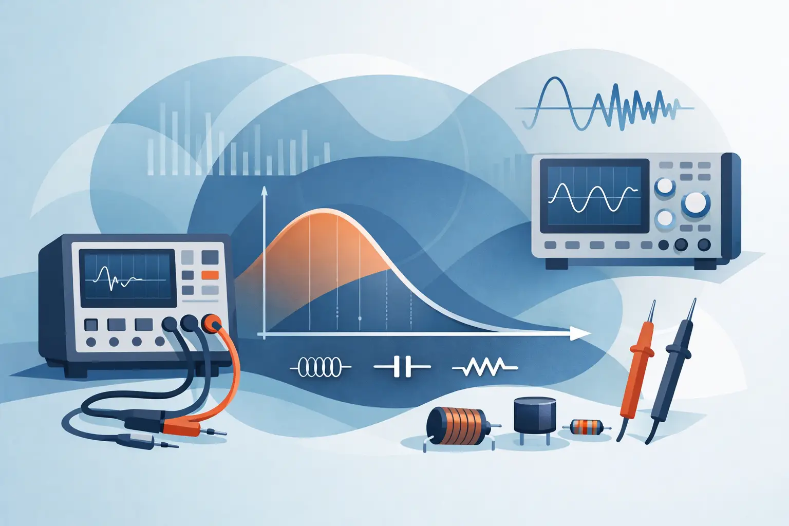
A 100 nF ceramic capacitor can look excellent at 1 kHz and completely different at 1 MHz. A power inductor that measures correctly at a small audio-frequency test signal may lose useful inductance under its actual switching conditions. That is why an impedance measurement frequency guide is not just a meter setting reference. Test frequency determines which electrical behavior the instrument sees.
For component identification, a single automatic test frequency is often the fastest practical choice. For design verification, incoming inspection, failure analysis, or troubleshooting frequency-sensitive circuits, the selected frequency must reflect the component, its construction, and its intended operating environment.
Why Frequency Changes an Impedance Reading
Impedance is the total opposition a component presents to AC. It includes resistance and reactance. Resistance dissipates energy; reactance stores and returns it through capacitance or inductance. For an ideal resistor, impedance does not change with frequency. Real parts are not ideal.
For a capacitor, capacitive reactance decreases as frequency rises:
`Xc = 1 / (2πfC)`
For an inductor, inductive reactance increases as frequency rises:
`Xl = 2πfL`
Those relationships explain the basic trend, but parasitic effects determine what happens in real components. Capacitors have equivalent series resistance (ESR) and equivalent series inductance (ESL). Inductors have winding resistance, core loss, interwinding capacitance, and possible core saturation. Resistors have lead inductance, body capacitance, and frequency-dependent construction effects.
An LCR meter applies an AC test signal, measures voltage and current, then calculates impedance magnitude and phase. From those values, it derives resistance, capacitance, inductance, ESR, dissipation factor, quality factor, or other parameters. When frequency changes, the phase angle and the contribution of parasitic elements change too. The displayed value can therefore change even when the component itself is healthy.
Impedance Measurement Frequency Guide: Start With the Job
The best test frequency depends on what you need the reading to prove. There is no universal frequency that is equally correct for every capacitor, inductor, resistor, or fault-finding task.
For fast SMT identification, use the instrument’s automatic mode unless the part is known to be frequency-sensitive. Automatic component recognition and parameter selection reduce handling time and are particularly useful when sorting unknown passive components or checking populated boards.
For specification verification, start with the manufacturer test conditions. A capacitor’s nominal capacitance may be specified at 120 Hz, 1 kHz, or 10 kHz. Inductance may be specified at 1 kHz, 10 kHz, 100 kHz, or a DC-biased operating condition. Measuring a part at a different frequency does not necessarily mean the meter or component is wrong. It may simply mean the result is not directly comparable to the published specification.
For circuit troubleshooting, choose a frequency close to the circuit’s relevant behavior when possible. An output capacitor in a switching power supply should not be evaluated only at 120 Hz if its ESR at tens or hundreds of kilohertz is the concern. Likewise, an RF inductor cannot be fully characterized by a 1 kHz inductance measurement.
Practical Frequency Ranges by Component Type
The following ranges are useful starting points, not fixed rules. Package size, dielectric, core material, value, bias, and intended application can change the preferred setting.
| Component or task | Typical starting frequency | What to watch for | |—|—:|—| | Large electrolytic capacitors | 100 Hz to 1 kHz | ESR, leakage effects, and capacitance tolerance | | Film capacitors | 1 kHz | Stable capacitance with low loss is common | | MLCC ceramic capacitors | 1 kHz to 100 kHz | DC bias, dielectric class, and self-resonance | | Small-value capacitors | 100 kHz to 1 MHz | Fixture parasitics become significant | | Power inductors | 1 kHz to 100 kHz | Core loss, DC bias, and self-resonant frequency | | RF inductors | 100 kHz to 1 MHz or higher | Self-resonance and test fixture compensation | | General resistors | 1 kHz | Most values remain primarily resistive | | Low-ohm resistors and shunts | Low-frequency AC or DC method | Lead/contact resistance and Kelvin connection quality |
Capacitors: Measure Below Self-Resonance
Every practical capacitor reaches a self-resonant frequency. Below resonance, it behaves primarily as a capacitor. At resonance, capacitive and inductive reactance cancel. Above resonance, ESL can make the device appear inductive.
This is especially relevant for small MLCCs. A low-value capacitor intended for high-frequency decoupling can have a self-resonant frequency within the range of an advanced LCR meter. If the display changes from capacitance to inductance as frequency increases, that transition may be normal behavior rather than a failed part.
Electrolytic capacitors require a different perspective. Their capacitance is often measured at relatively low frequency, while ESR becomes more useful at frequencies related to power-conversion ripple. A good inspection process records both the capacitance test condition and the ESR test condition. A capacitance value alone can miss a dried-out capacitor with elevated ESR.
Inductors: Inductance Is Not Constant at Every Frequency
Inductor datasheets commonly state an inductance test frequency because inductance depends on frequency and excitation level. Ferrite, powdered iron, and other core materials have different loss characteristics. As test frequency rises, core loss and parasitic capacitance can affect the calculated result.
DC bias is another limitation. Most handheld LCR measurements use a small AC test signal and do not replicate the DC current present in a buck converter or power rail. An inductor may pass a low-signal inductance test yet lose inductance when its core is biased near saturation. Use the LCR result to identify the part and check for obvious faults, then compare against the application’s current and bias requirements.
As an inductor approaches self-resonance, its distributed capacitance dominates. The apparent inductance can rise sharply, become unstable, or change to capacitive behavior. A reading in that region is not useful as a normal inductance value.
Resistors: Frequency Usually Matters Less, Until It Does Not
At low and moderate frequencies, most resistors measure close to their marked resistance. Frequency becomes more relevant with low-value shunts, wirewound resistors, high-value resistors, and RF components. Wirewound parts can be inductive. Thick-film chip resistors have parasitics that become relevant at high frequency. Very high resistance values can be affected by fixture leakage, contamination, and stray capacitance.
For milliohm-range measurements, lead resistance can be larger than the device under test. Use a four-wire Kelvin method whenever the instrument and fixture support it. The purpose is not merely better accuracy on paper. It separates the component resistance from probe, contact, and connection resistance that otherwise distort the reading.
Test Signal Level Matters Along With Frequency
Frequency is only one part of the measurement condition. The AC test level can change results for nonlinear components. High-K ceramic capacitors can show capacitance variation with DC bias. Inductors can respond differently as excitation increases. Semiconductor junctions and in-circuit paths can also produce misleading readings when the test signal forward-biases a junction.
For reliable comparisons, keep frequency, signal level, fixture, and connection method consistent. If an incoming inspection record says a capacitor measures 9.8 µF at 1 kHz, that result is meaningful only when the next measurement uses comparable conditions.
Fixture Compensation Is More Important at Higher Frequency
At 1 MHz, a few millimeters of probe separation, oxidized tweezer tips, or an uncorrected fixture can contribute enough capacitance and inductance to affect a small component reading. Open and short compensation remove predictable fixture effects from the measurement path.
Perform open compensation with the test terminals in their normal measurement position and no component connected. Perform short compensation using a clean, low-impedance short at the same contact location used for the part. Repeat compensation after changing probes, adapters, or measurement frequency ranges when the instrument procedure requires it.
For small SMT components, stable contact pressure matters. Tweezer-style instruments such as LCR-Reader models reduce lead length and make direct component contact practical, but clean conductive tips are still essential. If values jump between measurements, inspect the contact surfaces before assuming the component is unstable.
A Fast Decision Process for Choosing Frequency
Begin with the component datasheet or the circuit’s operating range. If neither is available, use automatic measurement for an initial identification, then test at two or three appropriate frequencies when the result appears questionable. A capacitor that changes modestly across its expected range may be normal; one that shows excessive loss, erratic phase, or an unexpected resonance may deserve further investigation.
Do not force a component into a capacitance or inductance interpretation when the phase behavior says otherwise. Near resonance, the displayed primary parameter can be less informative than impedance magnitude, phase, and ESR. For troubleshooting, those secondary values often reveal whether a component is behaving as expected in the frequency range that matters.
A useful measurement is not simply the most precise number on the screen. It is the number obtained under conditions that match the specification, the circuit, or the fault you are trying to find. Select frequency with that purpose in mind, document the condition when results matter, and the LCR reading becomes a dependable engineering decision rather than an isolated value.