
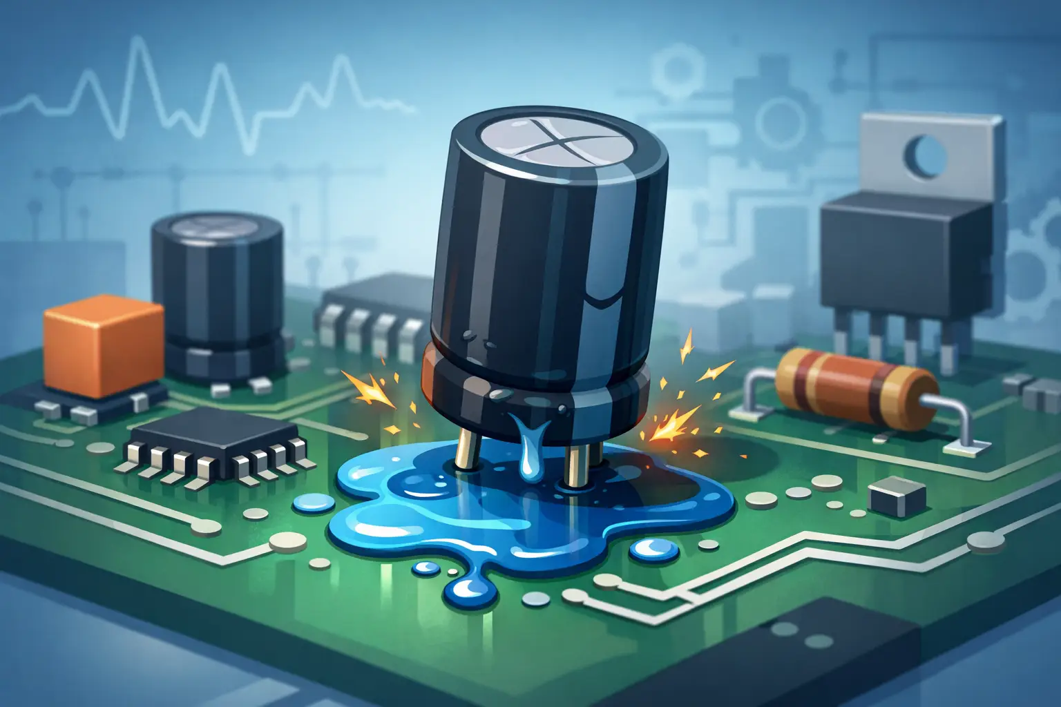
A capacitor that measures close to its marked capacitance can still be the source of a difficult fault. In power rails, timing circuits, battery-powered products, and analog stages, the question of what causes capacitor leakage is really a question of insulation integrity. When a capacitor permits more DC current than its design allows, it can drain a battery, shift a bias point, prevent a supply from starting, or create a failure that appears only after warm-up.
Capacitor leakage is not always visible. It may occur inside an otherwise normal-looking MLCC, film capacitor, tantalum capacitor, or aluminum electrolytic. It is also distinct from electrolyte escaping from a damaged aluminum electrolytic capacitor, although that physical leakage is often evidence that electrical performance has already deteriorated.
What Causes Capacitor Leakage?
At its simplest, capacitor leakage is caused by an imperfect insulating barrier between the capacitor’s conductive plates. No real dielectric is a perfect insulator. A small leakage current is expected and is specified by the manufacturer, particularly for electrolytic capacitors. The failure concern begins when leakage rises above the specified value, becomes unstable, or is high enough to affect circuit operation.
The underlying mechanism depends on capacitor technology. Ceramic capacitors use a ceramic dielectric, film capacitors use a polymer film, aluminum electrolytics depend on an oxide layer maintained by electrolyte, and tantalum capacitors rely on a tantalum oxide dielectric. Each material has different strengths, aging behavior, and failure modes.
Dielectric defects and material degradation
The dielectric must withstand the applied electric field without creating a conductive path. Manufacturing defects, microscopic voids, impurities, uneven dielectric thickness, and mechanical damage can reduce that margin. Over time, heat, humidity, electrical stress, and chemical exposure can further weaken the material.
In aluminum electrolytic capacitors, the oxide layer can degrade during long storage without voltage applied. When power is restored, leakage current may initially be elevated while the oxide reforms. This is why reforming procedures are sometimes used for stored high-voltage electrolytics. It is not a justification for applying uncontrolled voltage to an unknown part: current limiting is essential.
Tantalum capacitors can develop localized dielectric weaknesses that produce high leakage or a short circuit. Their failure mode can be abrupt when the part is subjected to surge current or excessive voltage. Ceramic capacitors may develop tiny cracks that create intermittent leakage, especially after board flexure or thermal cycling.
Excess voltage, transients, and reverse polarity
Voltage stress is one of the most common causes of capacitor leakage. A capacitor operated near its rated voltage has less tolerance for spikes, charging surges, temperature rise, and normal production variation. Repeated transients can progressively damage the dielectric even if no single event produces an immediate short.
Reverse polarity is particularly destructive to polarized capacitors. Aluminum electrolytic and tantalum capacitors are designed for a specific DC polarity. Applying reverse voltage can break down the dielectric, increase leakage current, generate gas, and eventually cause venting, rupture, or catastrophic failure. A small reverse voltage may be tolerated only when the component data specifies it.
Voltage rating is not merely a checkbox. A 10 V capacitor on a nominal 9 V rail may be exposed to higher voltage during charging, adapter faults, load dumping, or switching-ripple overshoot. Appropriate derating depends on capacitor type, operating temperature, expected transients, and the consequences of failure.
Heat and ripple current
Temperature accelerates chemical and dielectric aging. Aluminum electrolytic capacitors are especially sensitive because electrolyte evaporation and internal chemical change increase with sustained heat. As the electrolyte deteriorates, equivalent series resistance, or ESR, often rises. Leakage can also increase as the oxide layer and internal structure degrade.
Ripple current creates internal heating through ESR. In a switching power supply, a capacitor may meet the voltage rating but still fail early if its ripple-current capability is inadequate. The resulting heat can dry an electrolytic capacitor, deform its seal, or accelerate dielectric damage.
Leakage itself is temperature dependent. A capacitor that appears acceptable on a cool bench may draw substantially more current at elevated operating temperature. Conversely, a cold measurement may temporarily hide a leakage-related fault. For intermittent failures, comparing cold and warm behavior is often more revealing than taking one reading.
Moisture, contamination, and board-level leakage
Not every apparent capacitor leakage fault originates inside the capacitor. Flux residue, conductive dust, absorbed moisture, electrolyte residue, process contamination, and damage to solder mask can create a parallel leakage path across the PCB. On high-impedance nodes, even microamp-level leakage across the board can be significant.
This distinction matters during repair. Removing a suspected capacitor and finding that the circuit still has low resistance to ground points to a board-level or downstream fault, not necessarily a bad capacitor. Inspect the area under and around the component, especially beneath large electrolytics and around fine-pitch parts where residues can remain trapped.
Moisture also affects high-value ceramic capacitors and insulation surfaces. Condensation, wash-process residue, and poorly cleaned flux can turn a stable circuit into one that fails only in humid conditions. Thorough cleaning and controlled drying are part of diagnosis, not cosmetic finishing.
Mechanical stress and cracked MLCCs
Surface-mount multilayer ceramic capacitors are compact and reliable, but they are vulnerable to flex cracking. Board bending during depanelization, connector insertion, screw tightening, poor support during handling, or thermal expansion mismatch can crack the ceramic body. The crack may be too small to see without magnification.
A cracked MLCC may become a direct short, show low insulation resistance only at a particular temperature, or behave normally until the board flexes. Capacitors near board edges, mounting holes, heavy connectors, and heat-producing components deserve particular attention. In these cases, replacing the component without addressing the mechanical cause can lead to repeat failures.
Electrical Leakage Versus Visible Electrolyte Leakage
Technicians use the word leakage in two ways. Electrical leakage means unwanted current through or around the capacitor. Physical leakage means electrolyte escaping from an aluminum electrolytic capacitor. The two can occur together, but they are not interchangeable.
Visible electrolyte residue, a lifted vent, a swollen can, corrosion at the leads, or a damaged rubber seal are strong replacement indicators. However, an electrolytic capacitor can have elevated ESR or leakage current with no visible external damage. Likewise, a clean-looking component may be electrically defective after surge stress or overheating.
How to Test a Suspected Capacitor
Capacitance and ESR readings are useful, but neither measurement alone proves low DC leakage. A capacitor can show a reasonable capacitance value and still leak excessively at its working voltage. Testing must match the suspected failure mechanism.
First, isolate the circuit safely. Disconnect power, discharge capacitors using an appropriate resistor, and verify residual voltage with a meter. Never short a charged high-energy capacitor directly with a tool. In-circuit readings can be misleading because semiconductors, resistors, and parallel capacitors create alternate current paths.
For a quick screening step, measure capacitance and ESR. A handheld tweezer-style meter such as an LCR-Reader can quickly identify a wrong-value, open, or high-ESR surface-mount capacitor and reduce the number of parts that need removal. For leakage diagnosis, however, use a controlled DC test near the capacitor’s normal operating voltage, within its rating, with a known current limit.
Apply the DC test voltage and observe current over time. A healthy capacitor may show a charging surge that decays. The relevant value is the stabilized current after the interval specified by the component manufacturer. Compare it with the leakage-current limit in the data sheet, which is often expressed as a fixed microamp value or a formula based on capacitance and rated voltage.
If current remains high, rises with time, or varies sharply with light pressure or temperature, remove the capacitor from the circuit if practical and repeat the test. An out-of-circuit result separates component failure from PCB contamination or another parallel path. For low-voltage circuits, an insulation-resistance meter may apply too much voltage, so choose test equipment and voltage carefully.
Preventing Leakage-Related Failures
Prevention begins with correct component selection. Choose voltage margin appropriate to the application, verify ripple-current and temperature ratings, and use polarized capacitors with the correct orientation. In high-reliability work, consider expected surge conditions rather than relying only on nominal rail voltage.
Layout and assembly practices matter just as much for SMT parts. Keep MLCCs away from high-flex locations when possible, orient them to reduce stress from board bending, use controlled soldering profiles, and avoid aggressive depanelization. Clean residues from high-impedance areas and investigate any source of moisture ingress before replacing components.
When a capacitor is suspected, do not stop at its capacitance marking or visible condition. Measure the electrical behavior that matters at the operating voltage, inspect the surrounding board, and account for heat, ripple, and mechanical stress. That approach turns a vague leakage complaint into a repeatable repair decision.