
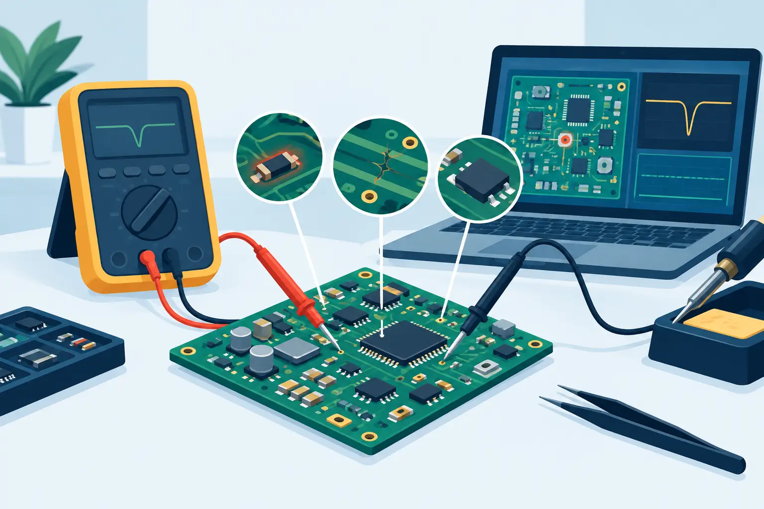
A board that will not power up rarely announces the failed part. It may show a dead short on a supply rail, an unstable regulator output, or a section that works only after warming up. Practical pcb repair measurement examples turn those symptoms into repeatable checks, helping a technician move from a suspect circuit area to a specific component without desoldering parts at random.
The measurement itself is only one part of the diagnosis. A useful result must be compared with the schematic, board markings, a known-good board, or the electrical behavior expected at that location. In-circuit measurements are fast and often decisive, but parallel paths can alter the reading. The goal is not to treat every displayed value as absolute truth. The goal is to use the value to make the next repair decision with confidence.
PCB Repair Measurement Examples for Common Faults
Example 1: Finding a shorted supply-rail capacitor
A device with no power is one of the most common repair cases. Before applying full power, measure resistance between the affected rail and ground. A 3.3 V or 5 V rail reading near zero ohms can indicate a shorted multilayer ceramic capacitor, a failed IC, solder bridge, or damaged connector.
Start at the power input or regulator output and use the board layout to work outward. If several capacitors are connected directly across the rail, measure each one. A capacitor that reads essentially as a short in resistance mode is suspicious, particularly when adjacent capacitors on the same rail read higher because of their location or circuit isolation.
This is not always a simple pass/fail test. Large processor rails can have low resistance by design, and a meter may show a low value while charging distributed capacitance. Compare the result with a known-good board when possible. If no reference board exists, isolate sections by removing jumpers, inductors, or zero-ohm links where the circuit design permits. The shorted side of the split rail becomes clear quickly.
Once the suspected capacitor is removed, measure the rail again. If the short disappears, measure the removed part out of circuit and inspect the pads for damage or solder debris before fitting a replacement.
Example 2: Confirming a cracked or open MLCC
A ceramic capacitor can crack after board flexing, impact, or thermal stress. Some cracked MLCCs become shorted, while others become intermittent or open. In an open condition, the circuit may exhibit regulator oscillation, excessive ripple, audio noise, or unreliable reset behavior.
Suppose a regulator requires a 10 uF output capacitor. With power removed, measure the capacitor in circuit. A reading far below the marked value may point to a damaged component, but nearby capacitors in parallel can make this measurement misleading. If the board has only one capacitor at that node, a near-zero capacitance result is meaningful. If several are in parallel, lift one terminal of the suspect part before deciding it has failed.
Inspection matters here. Look for a hairline fracture at the capacitor end cap, a component shifted off one pad, or a crack in the PCB beneath the part. Measurement and visual evidence should agree before replacement.
Example 3: Using ESR to identify a weak electrolytic capacitor
Capacitance alone does not establish that an electrolytic capacitor is serviceable. A part can remain close to its marked capacitance while its equivalent series resistance, or ESR, rises enough to disrupt a switching supply, audio amplifier, or control loop.
Consider a power supply that starts, then cycles or produces excessive output ripple. Compare the ESR of capacitors in the same circuit stage. A single capacitor reading substantially higher than similar parts of the same value and voltage rating deserves attention. The comparison is especially useful when a manufacturer datasheet or known-good unit is unavailable.
In-circuit ESR testing can be effective because low test voltages generally avoid turning on semiconductor junctions. Still, parallel capacitors can produce an artificially low ESR reading. A high reading is often more diagnostic than a low one in circuit. If a capacitor appears high-ESR and the symptom fits, remove it or isolate one lead for confirmation.
Example 4: Checking a resistor in a feedback network
A regulator output that is too high, too low, or unstable often leads technicians to replace the regulator IC first. That can waste time. The feedback divider resistors that set the output voltage are smaller, less expensive, and frequently exposed to heat or liquid contamination.
Measure each resistor with power removed. If a 100 kOhm resistor reads 130 kOhm, the difference may be enough to shift a precision feedback circuit. However, measure with care: a resistor connected to another path can read lower than its actual value because other components are effectively in parallel.
A resistor that reads higher than its marked value is usually more suspicious in circuit than one that reads lower. To verify a low reading, lift one end or consult the schematic. For small SMD resistors, tweezer-style probes allow direct contact on the end terminations without relying on test hooks that may slip onto neighboring pads.
Example 5: Testing a diode clamp or protection device
Data lines, charging inputs, and external connectors commonly use diode arrays or transient-voltage-suppression devices. After an overvoltage event, these parts may fail short and pull down a signal or supply line.
Use diode mode to compare the forward voltage drop from each protected line to ground and to the relevant supply rail. A normal silicon junction often shows a forward drop in one direction and open circuit in the reverse direction. Schottky devices typically show a lower forward drop. The exact number depends on the component, test current, temperature, and the circuit around it.
The useful clue is symmetry. On a multi-line protection array, one channel that reads near zero in both directions while the others behave normally is a strong fault candidate. Do not assume every low diode reading indicates a bad part, though. IC input structures can create valid diode paths. Compare identical channels or an equivalent connector on the board.
Example 6: Separating an inductor fault from a downstream short
Inductors in DC-DC converters and filter networks should have very low DC resistance. A continuity beep across an inductor is therefore normal and does not prove it is shorted. The relevant questions are whether the inductor is open, whether its resistance is unusually high, and whether a short exists beyond it.
Measure resistance across the inductor first. An open reading where a low resistance is expected suggests a cracked body, failed solder joint, or damaged winding. Then measure from each side of the inductor to ground. If the load side is near zero ohms and the source side is not, the downstream section is the likely location of the fault.
For a suspected open inductor, inductance measurement provides an additional check. But inductance values in circuit can be influenced by the converter IC, capacitors, and connected loads. Remove or isolate the part when the reading does not match the expected behavior.
A Measurement Sequence That Reduces Rework
The fastest troubleshooting process generally starts with passive checks before powered testing. Inspect for physical damage, measure supply rails to ground, verify fuses and zero-ohm links, then check the passive parts associated with the failed function. Applying power too early can obscure a fault, destroy a marginal component, or create misleading thermal symptoms.
Use the correct measurement mode for the question being asked. Resistance identifies shorts, opens, and drifted resistors. Capacitance checks decoupling and timing parts. ESR exposes aging electrolytics and some polymer capacitors. Diode mode helps locate failed protection devices and semiconductor junction problems. Inductance measurement can confirm a suspect coil, but only after considering what else is connected across it.
A handheld automatic LCR meter such as an LCR-Reader is particularly useful when moving between these checks on densely populated boards. Automatic component identification reduces mode changes, while fine tweezer probes provide controlled contact on small chip components. That speed is valuable only when paired with disciplined interpretation of the result.
When an In-Circuit Reading Is Not Enough
A component should be isolated when its reading conflicts with the symptom, when there are multiple parallel paths, or when replacement would involve significant rework. Removing every suspect part is not efficient. Lift one end of a resistor or capacitor, remove a series inductor, or separate a rail at an existing link to answer a specific diagnostic question.
Record values before and after isolation. A capacitor that appears to measure 40 uF in circuit may be part of a larger parallel bank, while its individual value may be 10 uF. A resistor reading 2 kOhm in circuit may actually be 10 kOhm with another path across it. The isolated measurement establishes whether the component itself is faulty or merely connected to a low-impedance circuit.
Good PCB repair is not about collecting measurements. It is about choosing the measurement that rules out the largest number of possibilities, then confirming only what the circuit evidence supports. That approach protects boards from unnecessary rework and gets equipment back to service faster.