
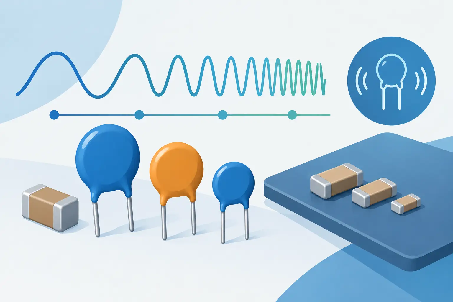
A 10 nF ceramic capacitor can appear entirely acceptable at 1 kHz and behave very differently when measured at 100 kHz or used in a high-frequency decoupling network. That is not necessarily a meter error. Ceramic capacitor frequency selection determines what electrical behavior is being measured, how the result compares with the data sheet, and whether the component is suitable for its actual circuit position.
For technicians sorting SMT parts, engineers validating a design, and quality teams checking incoming components, the right frequency is the one that answers the question at hand. A low-frequency reading may be best for identifying nominal capacitance. A higher-frequency measurement may better expose ESR, parasitic inductance, or a part that no longer performs in a switching circuit.
Why ceramic capacitors change with frequency
An ideal capacitor has capacitance only. Its reactance falls predictably as frequency rises:
`Xc = 1 / (2πfC)`
Real multilayer ceramic capacitors also have equivalent series resistance and equivalent series inductance. The electrode structure, termination geometry, PCB pads, probe contact, dielectric material, and nearby conductors all contribute to the measured result.
At relatively low frequencies, the capacitive behavior dominates and a meter can calculate a useful capacitance value. As frequency increases, ESR becomes more relevant. At still higher frequencies, lead and termination inductance can offset the capacitive reactance. At the component’s self-resonant frequency, capacitive and inductive reactance cancel. Above that point, the part behaves inductively rather than capacitively.
This is why a capacitance reading alone cannot describe high-frequency performance. A 1 uF MLCC may be a good bulk bypass component at one frequency range while a smaller-value capacitor with a higher self-resonant frequency provides better suppression at another.
Start with the measurement objective
Frequency selection should follow the intended decision, not a habit such as always measuring at 1 kHz. The same component can be tested at different frequencies for valid reasons.
If the task is component identification or value verification, use the data sheet’s stated test conditions whenever possible. Capacitor manufacturers commonly specify capacitance at 1 kHz for larger capacitance values and at 1 MHz or another higher frequency for smaller values, but there is no universal rule that applies to every series. The dielectric, nominal value, package, and manufacturer specification control the correct comparison point.
If the task is troubleshooting a switching power supply, RF stage, or digital rail, select a frequency that is relevant to the suspected fault and the meter’s available test frequencies. This will not replace an impedance analyzer or network analyzer for full frequency characterization, but it can quickly distinguish a normal component from one with an abnormal capacitance or loss reading.
For incoming inspection, consistency matters as much as frequency. Set one approved frequency, test level, fixture method, and acceptance range for each part number. Comparing measurements taken under mixed conditions creates false rejects and hides process variation.
Ceramic capacitor frequency selection by application
The following guide provides a practical starting point. Always defer to the component data sheet when checking a specified tolerance.
| Measurement purpose | Typical frequency approach | What to watch for | |—|—|—| | Value identification and sorting | Use the manufacturer-specified test frequency, often 1 kHz for many common values | Dielectric tolerance and DC bias can create large differences from the marked code | | Small-value RF capacitors | Use the higher available test frequency that matches the data sheet or application range | Fixture inductance and probe contact can dominate very small capacitance readings | | Power-rail decoupling checks | Measure capacitance and ESR at a frequency relevant to the converter or expected ripple range | A good low-frequency capacitance result does not prove high-frequency decoupling performance | | Failure analysis | Compare the suspect part and a known-good part under identical conditions at more than one frequency | Cracks, moisture damage, and termination faults may show up as changed loss or unstable readings |
A useful field method is to take measurements at two available frequencies when the instrument supports it. If the capacitance or dissipation factor changes much more than expected relative to a known-good sample, investigate the part, its solder joints, and the surrounding circuit. The result is comparative evidence, not a substitute for a complete impedance sweep.
Dielectric class matters more than many users expect
Ceramic capacitors are not one electrical family. Class 1 dielectrics, such as C0G or NP0, are designed for stability. Their capacitance changes minimally with temperature, voltage, time, and frequency compared with high-K dielectrics. They are common in timing, filtering, RF, and precision analog applications where predictable performance is required.
Class 2 dielectrics, including X7R and X5R, provide much higher capacitance in a small package. The trade-off is greater dependence on applied DC voltage, temperature, aging, and AC test conditions. A 10 uF X5R capacitor can lose a meaningful portion of its nominal capacitance under DC bias, especially in a small package or at a voltage rating close to its operating voltage.
Class 3 ceramics have even greater variation and are generally unsuitable where capacitance stability is critical. Frequency selection cannot correct for dielectric behavior. It only ensures that the meter reading is interpreted under a known, relevant condition.
When a measured Class 2 MLCC seems low, check the test frequency first, then test voltage, temperature, package size, rated voltage, and whether the component is measured in circuit. A low reading may be normal under the actual bias condition. It may also indicate a cracked component or an incorrect part installed on the board.
Test voltage and DC bias are part of the selection
Frequency is only one test parameter. The AC test signal amplitude affects nonlinear dielectric materials, while DC bias changes the effective capacitance of many high-K MLCCs. A meter reading taken with a small AC signal and no DC bias is valuable for identification, but it may not reproduce capacitance under operating conditions.
This distinction matters when troubleshooting power converters. A board may use several nominally identical 22 uF X7R capacitors, yet their effective capacitance differs because each location sees a different DC rail voltage. If the failure occurs only under load, compare the design’s bias derating data with the measured small-signal value before replacing components.
For precise correlation with a data sheet, match both the listed frequency and the stated test voltage. If the data sheet specifies a DC bias condition, a handheld LCR meter without bias capability cannot reproduce that exact result. The measurement remains useful, but the limitation should be documented.
Choose the right circuit model
Most LCR instruments report capacitance using either a parallel model, Cp, or a series model, Cs. At lower frequencies, high-impedance capacitors are often represented effectively by the parallel model. At higher frequencies, particularly where losses and ESR are more significant, the series model can be more meaningful.
The correct model depends on the component impedance and the instrument’s measurement method. Do not compare a Cp reading from one meter directly with a Cs value from another without confirming the frequency and equivalent circuit mode. The numerical difference can be significant for lossy capacitors.
Automatic instruments reduce setup time by selecting an appropriate measurement mode based on the detected component. For production checks or engineering documentation, record the displayed mode along with capacitance, frequency, and dissipation factor or ESR. A result without conditions is difficult to repeat and nearly impossible to defend during a quality review.
Avoid fixture and in-circuit measurement errors
At high frequency and low capacitance, the measurement setup can become the dominant error source. Long test leads add inductance. Dirty tweezer tips add resistance. A poor contact to an 0201 or 0402 component can create unstable readings that look like a damaged capacitor.
Use short connections, clean probe contacts, and a suitable open/short calibration procedure for the fixture. With tweezer-style meters, keep the component centered in the tips and avoid pressing hard enough to crack an MLCC. If values are near the instrument’s lower measurement limit, repeat the test with a known-good component of the same package and nominal value.
In-circuit readings require additional caution. Parallel components usually increase apparent capacitance, while semiconductors and connected power rails can distort the measurement. Discharge the circuit first. When the reading matters, isolate one end of the capacitor or compare it with the board schematic and a known-good assembly.
A practical workflow for faster decisions
Begin with the capacitor’s marking, board reference designator, and available bill of materials data. Identify the nominal value, dielectric, package, voltage rating, and circuit role. Select the manufacturer-specified frequency for value verification, then take a second reading at a higher relevant frequency if the application is switching or RF-related.
Compare like with like: same meter, same calibration state, same probe method, same frequency, and the same circuit condition. A handheld instrument such as an LCR-Reader is especially useful for this work because it can make quick contact with small SMT components without adding long leads that complicate the measurement.
The most useful capacitor measurement is not simply the closest number to the printed value. It is a repeatable result taken at a frequency and test condition that reflects the specification or failure mechanism you need to evaluate. That discipline turns a fast LCR reading into an informed engineering decision.