
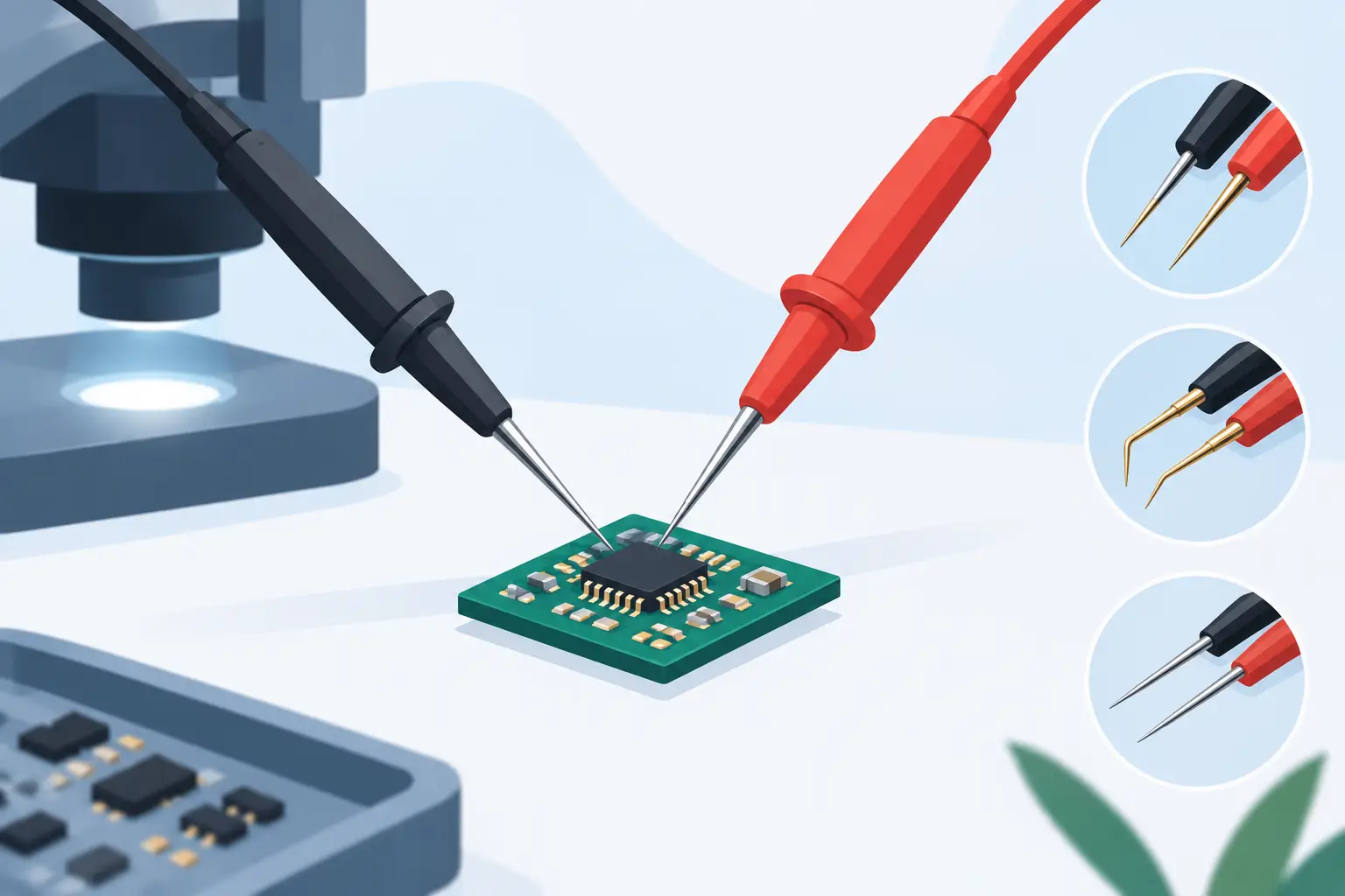
A 0402 capacitor can disappear under a conventional probe tip. A 0201 resistor gives you even less room for error: one slip can bridge adjacent pads, lift a part, or produce a reading dominated by contact resistance. The best probes for tiny components are not simply the sharpest probes available. They combine controlled contact force, adequate insulation, stable positioning, and measurement characteristics suited to the component and circuit.
For surface-mount troubleshooting, probe selection determines whether a measurement is repeatable or merely plausible. That distinction matters when sorting parts, verifying a rework result, locating a short, or measuring ESR on a populated board.
Why Standard Probe Tips Fall Short on SMT
Traditional multimeter probes are designed to contact test points, terminals, and larger leads. Their metal exposure is often too broad for fine-pitch work. Even a needle-style tip can be awkward when the operator must hold two separate probes steady while watching magnified components.
The issue is not tip diameter alone. A very sharp, uninsulated needle may reach a small pad, but it can also touch nearby copper, pierce solder mask, or skid off a solder joint. On densely populated boards, the safest probe is usually one that exposes only the small amount of metal required to make contact.
Electrical behavior matters as well. At low resistance values, lead resistance and unstable contact can materially affect the result. At higher test frequencies, long leads and poor fixture geometry add inductance and capacitance that can distort measurements. The correct probe design must match both the board geometry and the measurement task.
Best Probes for Tiny Components by Task
There is no single probe type that is best for every small component. The following options cover the most common repair, inspection, and production use cases.
Tweezer Probes for Individual Chip Components
Tweezer-style probes are generally the most efficient choice for loose chip resistors, capacitors, inductors, and diodes. Two opposing tips contact both terminations at once, eliminating the need to stabilize two handheld leads. This makes them particularly effective for 0402, 0201, and similarly small parts when access permits.
The key advantage is controlled geometry. The spacing between the tips is fixed by the tool, and the operator applies force directly along the component axis. That reduces accidental bridging and makes repeated measurements much faster than using two separate pointed probes.
For component identification and in-circuit troubleshooting, an LCR tweezer meter such as an LCR-Reader combines the probe form factor with automatic resistance, capacitance, inductance, and ESR measurement. The instrument can identify the component type and select test conditions without requiring manual mode changes. This is useful when a board contains mixed passive components and the technician needs a fast first measurement before deciding whether the part must be removed.
Tweezer probes do have a limitation: they need access to both ends of the component. They are less suitable when one termination is blocked by a connector, shield, neighboring package, or conformal coating.
Insulated Needle Probes for Crowded Boards
Fine insulated needle probes are a practical choice when tweezers cannot reach both terminals. Look for a narrow conductive tip with insulation extending close to the point. The insulation limits the exposed contact area, helping prevent shorts between adjacent pins and pads.
These probes work well for checking a single rail, IC pin, via, or exposed component end. They are also useful when measuring a component in circuit requires contacting one terminal while the other reference point is farther away.
The trade-off is operator control. Two separate hand probes demand a stable hand position, especially under magnification. For delicate work, secure the PCB in a holder and support your hands against the bench rather than hovering above the board. A sharp tip should touch the solder joint, not scrape along the pad.
Spring-Loaded Pogo Probes for Repetitive Testing
Spring-loaded pogo probes are best when the same points must be tested repeatedly. Their internal spring maintains more consistent contact pressure than a rigid needle, reducing variation caused by hand force. They are common in test fixtures, bed-of-nails systems, and production verification setups.
For tiny components, use a probe tip shape that matches the target. A conical or crown tip can grip a soldered pad, while a flat tip may be better for a larger exposed metal surface. Excess spring force is not an advantage on fragile pads. It can dent soft solder, move small parts, or damage a weakly bonded land.
Pogo probes are less convenient for one-off field repair because they need a holder, fixture, or deliberate hand positioning. Their value rises quickly when testing dozens or hundreds of similar assemblies.
Kelvin Probes for Low-Resistance Measurements
Two-wire measurement is often adequate for ordinary resistance checks, but it becomes less reliable as resistance approaches the lead and contact resistance of the test setup. Kelvin, or four-wire, probing separates the current path from the voltage-sensing path. This greatly reduces errors caused by probe leads and contact interfaces.
Use Kelvin probes when evaluating shunt resistors, low-value current-sense resistors, solder joints, traces, relay contacts, or other milliohm-level paths. A small component may physically accept a fine probe, yet still require Kelvin measurement for an accurate electrical result.
Kelvin connectors and clip-style fixtures are particularly helpful when verifying a known value outside the circuit. In-circuit measurements still require judgment because parallel paths can make any resistance reading appear lower than the component’s marked value.
What Tip Geometry Should You Choose?
Tip geometry should be selected for the contact surface, not just component size. For a clean soldered chip component, narrow flat or lightly rounded tweezer tips often make reliable contact without digging into solder. For a small test pad or IC lead, insulated needle tips offer better isolation. For repeated access to a defined pad, spring-loaded points provide consistency.
Avoid assuming that the finest possible point is always better. Extremely sharp tips wear quickly and can puncture solder mask or leave grooves in pads. A slightly broader, well-insulated tip is often safer and more repeatable when the target is a standard SMT solder joint.
Also consider tip material and finish. Tips should resist oxidation and be easy to clean. Oxidized surfaces create unstable contact and may cause readings to drift as pressure changes. Cleaning the tip with an appropriate electronics-safe method is often the fastest way to resolve inconsistent measurements.
Probe Force, Stability, and Board Protection
Small components tolerate limited mechanical force. A chip capacitor can crack internally if it is pressed sideways, while a tiny resistor can be displaced during rework inspection if the probe slips. Use only enough force to establish electrical contact.
Board support is equally important. Place the assembly on a stable, non-slip fixture. Magnification and adequate lighting help more than many users expect, especially when distinguishing a component termination from a neighboring pad or solder bridge.
Before measuring, inspect the target area for flux residue, corrosion, cracked solder, or conformal coating. Probes cannot compensate for a contaminated contact surface. If readings change significantly with probe pressure or position, treat the result as suspect and inspect the joint before replacing the component.
Match the Measurement Method to Circuit Conditions
Even the best probe cannot make an in-circuit reading behave like an isolated component measurement. Parallel resistors lower apparent resistance. Nearby capacitors add capacitance. Semiconductor junctions and powered rails can alter the test result or place the instrument at risk.
Power down the circuit and discharge capacitors before connecting LCR or resistance probes. For a questionable reading, compare it with the same location on a known-good board, inspect the schematic if available, or remove one end of the component when the diagnosis requires a definitive value.
For capacitance and ESR checks, short leads and stable contact are especially valuable. For inductors, keep probe geometry consistent and recognize that nearby conductive structures can influence the measurement. Measurement speed is useful, but repeatability is what supports a repair decision.
A Practical Selection Rule
Choose tweezer probes when both ends of a tiny passive component are accessible and speed matters. Choose insulated needle probes for isolated pads, IC pins, and locations with restricted access. Use pogo probes for repetitive test points, and use Kelvin probes whenever low-resistance accuracy is the priority.
The most productive setup is often more than one probe type. Fine insulated needles handle board access, tweezers handle individual SMT parts, and Kelvin connections verify low-ohm work. Keep the tips clean, inspect them for wear, and select the least aggressive contact method that produces a stable reading.
Tiny components do not require guesswork. With probe geometry matched to the pad, component, and measurement range, the reading becomes faster to obtain and far easier to trust.