
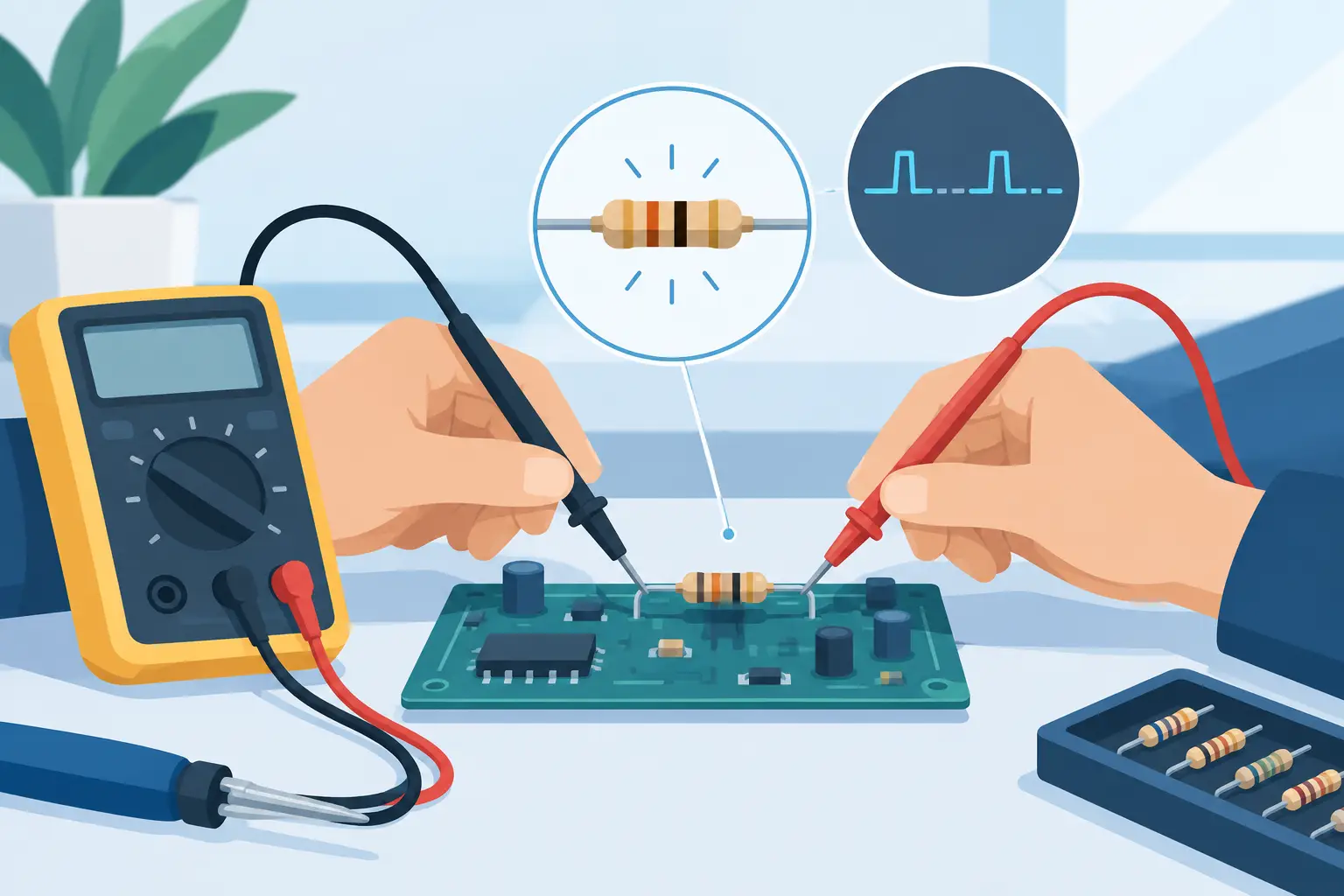
A resistor that measures correctly once and fails the next time is rarely a mystery solved by a single resistance reading. The fault may appear only when the board is warm, flexed, vibrating, humid, or carrying normal operating current. Knowing how to troubleshoot intermittent resistors means testing the component, its terminations, and the surrounding circuit as one fault system.
Intermittent behavior deserves priority in repair and production work because it can create failures that disappear at the bench and return in service. A board may reset, a bias voltage may drift, an LED may flicker, or a protection circuit may trip with no obvious permanently damaged part. The goal is not simply to find a resistance value. It is to reproduce the condition that makes that value, or its connection, unstable.
Start by defining the failure condition
Before probing the resistor, record exactly when the fault occurs. Does the failure begin after five minutes of operation? Does pressing on a connector, tapping the PCB, or moving a cable cause the symptom? Is it tied to a particular supply voltage, load current, board orientation, or temperature?
This information determines the test method. A resistor with a cracked film may change value as it heats under load. A sound resistor with a fractured solder joint may remain stable until the board flexes. Leakage from contamination can be more evident in humid conditions, while a marginal connector or via can imitate a failed pull-up or current-sense resistor.
Use the circuit symptom to narrow the expected effect. For example, an intermittent series resistor can interrupt a signal or supply path. An unstable pull-up or pull-down resistor can leave a logic input floating. A changing divider resistor can shift a reference voltage. In a current-sense position, even a small resistance change can affect regulation, overcurrent protection, or reported measurements.
Inspect the resistor and the complete current path
Visual inspection is fast, but it must go beyond checking whether the resistor looks burned. Under magnification, inspect both ends of the component, the pads, nearby vias, and copper traces leading to the next node. A darkened body, lifted termination, cracked chip, corroded pad, or solder joint with a visible ring is useful evidence. It is not proof by itself.
Surface-mount resistors can develop hairline cracks that are difficult to see, especially after board flexure or thermal cycling. Thick-film chip resistors are particularly susceptible to resistance shifts if the substrate is stressed. Larger through-hole resistors can also fail at the lead-to-body transition, where repeated vibration or bending work-hardens the lead.
Look for conditions that produce mechanical stress: a resistor mounted close to a board edge, beside a screw hole, under a heat sink, or near a connector that receives repeated force. Also inspect heavy components and cable harnesses. Their movement can flex a board far from the point where force is applied.
Contamination matters more in high-impedance circuits. Flux residue, moisture, conductive dust, electrolyte residue, and corrosion can create alternate paths around a resistor or between adjacent pads. In those cases, the resistor may be electrically sound while the circuit node is not.
Measure correctly before calling the resistor bad
A resistance measurement made in circuit is a screening test, not always a component verdict. Parallel paths can make the displayed value lower than the resistor’s marking. Semiconductor junctions, capacitors charging from the meter stimulus, and active circuitry can create readings that drift or appear inconsistent.
First, power the circuit down. Disconnect external power sources and discharge capacitors where required. Verify that stored energy is not present before using a low-resistance measurement method or handling the board. Do not measure resistance on a powered circuit unless the instrument and procedure specifically support the intended live measurement.
Measure the resistor several times without moving the probes. Then apply light, controlled pressure to the board nearby, not directly through a fragile component body. Gently flex the board only within a safe range and observe whether the measurement opens, jumps, or becomes noisy. If the reading changes when the probes move, separate a probe-contact problem from a board fault by cleaning the pads and repeating the test.
For low-value resistors, probe and lead resistance can be larger than the expected change. Use Kelvin measurement when practical, especially for current-sense resistors and values below a few ohms. A two-wire handheld reading may be adequate for a 10 kOhm bias resistor, but it is not the right basis for judging whether a 0.05 Ohm shunt has drifted.
An LCR-Reader tweezer-style meter is useful for quickly checking small SMD resistors because the two contacts can engage the component terminations directly. Where circuit loading makes the result questionable, lift one end of the resistor or remove it and measure again. That isolation step is often faster than trying to interpret an in-circuit value against an unknown parallel network.
Use heat, cooling, and stress to reproduce the fault
Intermittent resistor faults usually reveal themselves when the original stress is recreated. Apply one variable at a time so the result remains meaningful. Monitor the resistance directly when possible, or monitor the circuit voltage, current, waveform, or functional output that changes when the fault occurs.
A practical sequence is to begin at room temperature, warm the suspect area gradually, then allow it to cool. Localized heat can expose a cracked resistive element, a poor termination, or a solder joint with different expansion behavior from the pad and component. Controlled cooling can produce the opposite transition. Avoid excessive thermal shock, especially near ceramic capacitors, plastic connectors, and temperature-sensitive devices.
Mechanical testing should be deliberate rather than aggressive. Use a nonconductive tool to apply slight pressure beside the resistor, along the trace, at nearby vias, and at connectors that may transfer stress into the PCB. If the circuit recovers or fails repeatedly with a particular movement, document the location and inspect that area under magnification.
For a powered functional test, measure the voltage drop across the resistor during normal operation. Ohm’s law provides a useful cross-check: resistance equals voltage drop divided by current. If the voltage drop changes while current should be stable, either the resistor, its solder connection, or the current path may be intermittent. If current changes with the load, the resistor may be responding normally and the root cause may be elsewhere.
Separate resistor failure from connection failure
A true intermittent resistor is less common than an intermittent connection. This distinction prevents unnecessary component replacement and repeat repairs. Compare the evidence before deciding which failure mode fits.
| Observation | More likely cause | Best confirmation | |—|—|—| | Resistance changes with body temperature after removal | Damaged resistive element | Repeat measurement through heat and cool cycles | | Reading opens when the board is flexed but component value is stable off-board | Cracked solder joint, pad, trace, or via | Inspect and continuity-test each termination path | | Circuit works when the component is pressed but not when its leads are probed | Weak solder fillet or pad attachment | Rework joint and inspect pad integrity | | In-circuit value is unstable but off-board value is stable | Parallel circuit path or contamination | Isolate node and clean the board |
When checking a solder joint, do not rely only on appearance. A joint can look acceptable while an internal crack opens under strain. Continuity testing from the resistor termination to the next accessible node is often more revealing than measuring across the resistor alone. Test both sides of the part. A resistor cannot control a circuit reliably if either end loses connection.
If rework is required, use the correct process for the board and package size. Excessive heat or mechanical force can damage pads, nearby components, or the resistor itself. After rework, repeat the stress test that originally produced the failure. A stable room-temperature reading is not enough to validate an intermittent repair.
Know when the measurement is misleading
Some apparent resistor faults originate in active components. A transistor, IC input, regulator, or protection device can change its loading as it warms, making a bias resistor appear to drift in circuit. Capacitor leakage may also pull a node down only after voltage is applied. In these cases, the resistor is reporting the problem rather than causing it.
Be cautious with resistor networks and arrays. A cracked common terminal or damaged internal connection can affect several channels at once, while individual resistance measurements may look plausible. Measure each element against the common pin and compare channels where the circuit design allows it.
High-value resistors require clean handling and clean measurement surfaces. Finger oils, flux, and moisture can materially affect megohm-range work. Low-value resistors require low-resistance techniques and attention to thermal EMF, probe pressure, and test current. The correct method depends on the resistor value, circuit role, and expected failure mechanism.
Document the repair so the fault does not return
Record the original symptom, the stress that reproduced it, the measurements observed, and the repair performed. In production or recurring field repairs, that record can expose a pattern such as a specific PCB lot, placement location, resistor package, assembly process, or mechanical loading condition.
After replacing a suspect resistor, verify its value and tolerance, power rating, temperature coefficient, voltage rating, pulse capability, and package size. Substituting a nominally equal resistance with an unsuitable part can create a new intermittent issue under load. For current sensing, divider networks, and precision analog circuits, tolerance and temperature coefficient may be as important as the printed value.
The most productive troubleshooting habit is to treat an intermittent resistor report as a request for evidence, not a request to swap a part. Reproduce the symptom, isolate the measurement, apply the relevant stress, and confirm the repair under the same conditions. That process turns a frustrating, disappearing fault into a repeatable engineering result.