
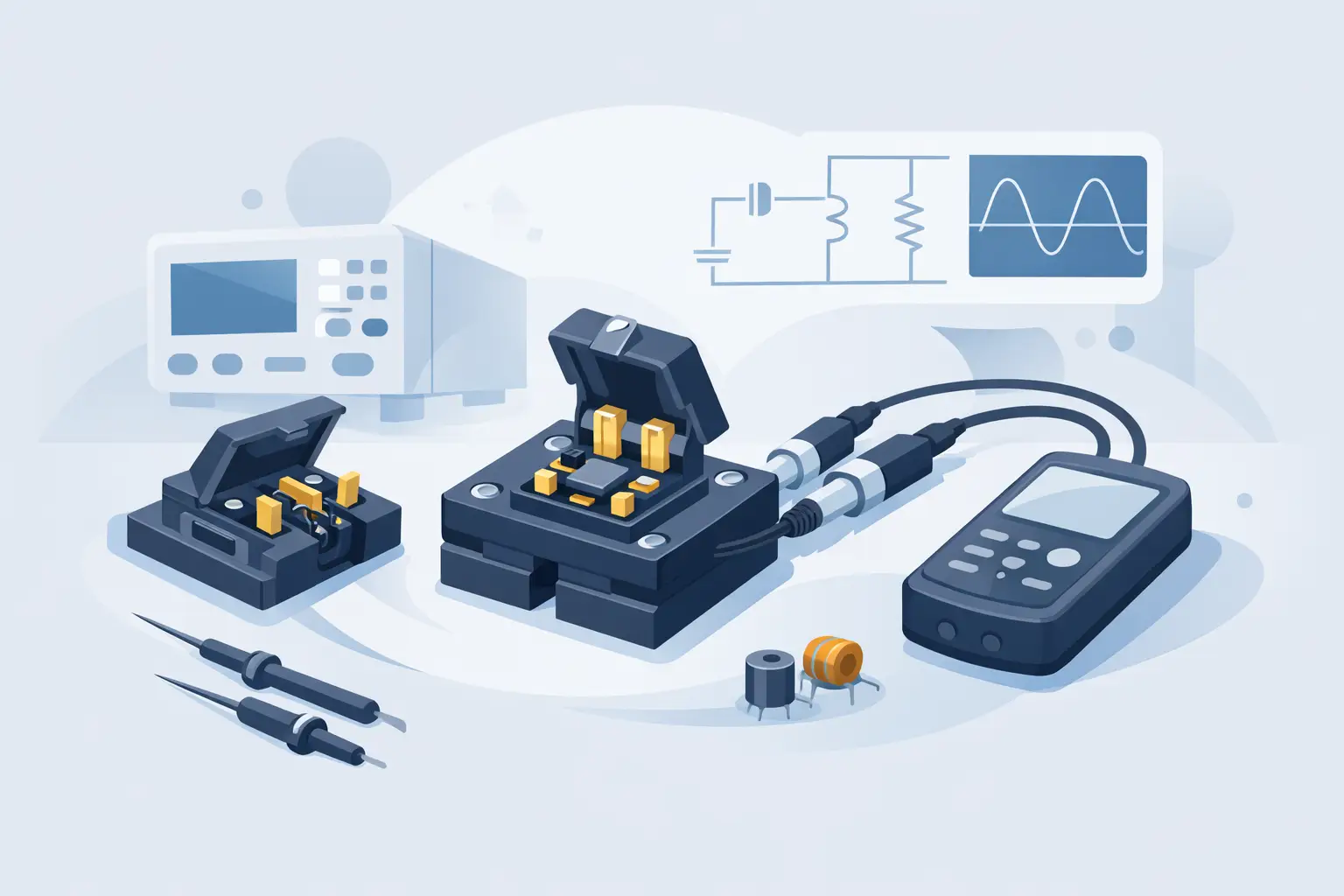
A component can be perfectly good and still produce a questionable reading when the connection between the meter and the device under test is poorly controlled. Calibration fixture adapters provide that control. They create a repeatable electrical and mechanical interface between an LCR meter, test tweezers, Kelvin probes, or a dedicated fixture and the component being measured.
For engineers, repair technicians, and quality-control teams, the adapter is not a minor accessory. At low resistance, low capacitance, high frequency, or when evaluating small SMT parts, fixture behavior can become a meaningful part of the measurement. Contact resistance, lead inductance, stray capacitance, and unstable pressure may all appear in the result unless the measurement setup is designed and compensated correctly.
What a Calibration Fixture Adapter Does
A calibration fixture adapter connects a test instrument to a known calibration standard or measurement fixture while preserving a defined measurement path. Depending on the instrument and application, it may provide dedicated terminals, Kelvin connections, a socket for a calibration component, or a mechanical interface for probe tips.
Its purpose is twofold. First, it makes calibration and compensation repeatable. Second, it reduces the uncertainty introduced by improvised leads, loose clips, worn contacts, and inconsistent component placement. A properly designed adapter gives the instrument the same electrical geometry each time a reference standard or production component is connected.
This matters because an LCR meter does not measure a component in isolation. It measures the complete path between its input terminals and the device under test. If that path adds resistance or reactance, the instrument may include part of the fixture in the displayed value.
For a 10 kOhm resistor, a small amount of contact resistance may be insignificant. For a 0.1 Ohm shunt resistor, milliohm-range connection error can dominate the result. The same principle applies to low-value capacitors, where fixture capacitance can be comparable to the component itself, and to inductors measured at frequencies where lead length is no longer electrically negligible.
Why Calibration Fixture Adapters Affect Results
The most useful adapter is not necessarily the most elaborate one. It is the one that matches the instrument, component package, measurement range, and required uncertainty. Four characteristics determine whether an adapter supports reliable work:
- Low and stable contact resistance is essential for low-ohm resistance and ESR measurements.
- Controlled parasitic capacitance and inductance matter when measuring small capacitances, low inductances, or components at higher test frequencies.
- Kelvin separation keeps source and sense paths independent, reducing voltage-drop errors in low-impedance measurements.
- Repeatable positioning and pressure prevent the reading from changing each time an operator inserts or touches a part.
An adapter can improve repeatability without automatically improving absolute accuracy. Absolute accuracy still depends on the meter’s specification, calibration status, selected test frequency, test signal level, and the quality of the standards used. The adapter simply removes a major source of avoidable variation.
Contact Resistance Is Not a Constant
Oxidation, flux residue, probe-tip wear, and insufficient clamping force can all increase contact resistance. More importantly, they can make it variable. A reading that changes as a component is moved slightly is often a connection problem before it is a component problem.
This is especially common with small chip resistors, MLCC capacitors, and components removed from a board. Their terminals may be oxidized, damaged during rework, or covered with solder residue. Clean contacts and consistent placement are basic requirements before interpreting a marginal result as a failure.
Parasitics Become Significant at Small Values
Every adapter and fixture has its own capacitance and inductance. A pair of exposed contacts separated by insulating material has capacitance. A conductive path between the meter and component has inductance. Neither effect can be eliminated completely, but both can be characterized and compensated.
For example, an adapter used to measure a 1 uF capacitor may contribute too little capacitance to matter in practical troubleshooting. That same adapter could materially affect a 10 pF capacitor measurement. Likewise, the lead inductance of an adapter may have little effect on a larger power inductor but complicate a low-nanohenry measurement.
That is why open and short compensation procedures are tied to the actual fixture configuration. Changing the adapter, adding a lead extension, or changing probe geometry can invalidate a previous compensation.
Open and Short Compensation: Use the Actual Setup
Most precision LCR measurement workflows use open and short compensation to account for fixture effects. The exact sequence depends on the instrument manual, but the principle is consistent.
During open compensation, the instrument characterizes the residual admittance of the fixture with no component installed. This helps account for stray capacitance and leakage paths. During short compensation, the instrument characterizes residual impedance with the measurement terminals shorted at the device-under-test location. This addresses lead resistance and inductance.
The critical detail is location. A short applied at the meter input does not adequately compensate for an adapter, extension, or fixture located farther down the path. The open and short conditions should be created where the component will actually be measured.
After compensation, avoid changing the fixture geometry. Moving a Kelvin probe, swapping adapters, spreading contacts apart, or using a different socket can alter parasitic values. For routine production work, document the adapter and compensation state as part of the test method.
Choosing an Adapter for Your Measurement Task
Select the interface based on the component and the measurement objective, not merely on what is physically convenient. Tweezer-style instruments are often the fastest option for loose SMT components and in-circuit comparison work because the probe spacing and handling are integrated. A dedicated fixture adapter can be preferable when testing the same package repeatedly, measuring parts that cannot be gripped reliably, or maintaining a documented quality-control process.
For low-resistance and ESR work, prioritize true Kelvin connections and firm, clean contact surfaces. Two-wire adapters can be useful for general-purpose checks, but their lead and contact resistance are included in the measurement path. A four-terminal arrangement is better when small resistance differences matter.
For capacitance and inductance measurements near the lower end of an instrument’s range, choose the shortest practical connection path. Avoid adapters with unnecessarily long flying leads. Shielding may help in electrically noisy environments or when measuring very small capacitance values, but it must be part of the compensation procedure.
For production testing, consider operator repeatability. A fixture that holds a 0402 or 0603 component in a consistent orientation can reduce handling time and help prevent false rejects. For repair work, speed may be more valuable than a specialized socket. In that case, clean test tweezers and regular verification against a known component can provide a practical balance.
Verification Is Different From Calibration
Calibration fixture adapters support calibration, but they are not calibration certificates by themselves. Calibration establishes how closely an instrument performs against traceable standards under defined conditions. Verification is the day-to-day check that the instrument and fixture are still behaving as expected.
A useful verification routine compares readings against stable reference components with values relevant to the work being performed. A technician troubleshooting power supplies may keep a known low-ESR capacitor and low-ohm resistor. An assembly team screening SMT inventory may use representative resistor, capacitor, and inductor standards.
If the reference reading shifts unexpectedly, isolate the cause before adjusting the instrument. Inspect the adapter contacts, probe tips, connector seating, contamination, battery condition where applicable, and compensation state. Repeating the measurement with a second known component helps distinguish fixture drift from a problem with the reference part.
LCR-Reader instruments are designed to reduce setup work through automatic component identification and test parameter selection, but controlled contact conditions remain essential when measurements approach the limits of a component or instrument range. Automation speeds the decision process. A clean, compensated adapter helps ensure the decision is based on the component rather than the test path.
Maintenance Practices That Preserve Repeatability
Treat the adapter as a precision interface. Store it where contacts are protected from dust, oils, and moisture. Do not use abrasive cleaning methods that remove plating or alter contact geometry. When cleaning is necessary, use an appropriate electronics-safe method and allow the contacts to dry completely before measurement.
Inspect spring contacts and probe interfaces for wear, weak return force, pitting, or accumulated residue. Replace damaged fixtures rather than compensating around visibly unreliable contact surfaces. Also check connectors for strain damage, particularly on adapters that are frequently moved between bench stations.
The best time to detect adapter problems is before a questionable measurement reaches a repair record or production report. A quick reference check at the start of a shift can prevent hours of unnecessary component sorting.
A calibration fixture adapter earns its place on the bench when it turns a variable connection into a known one. Keep the path short, the contacts clean, the compensation current, and the reference checks relevant to the components you measure most often.