
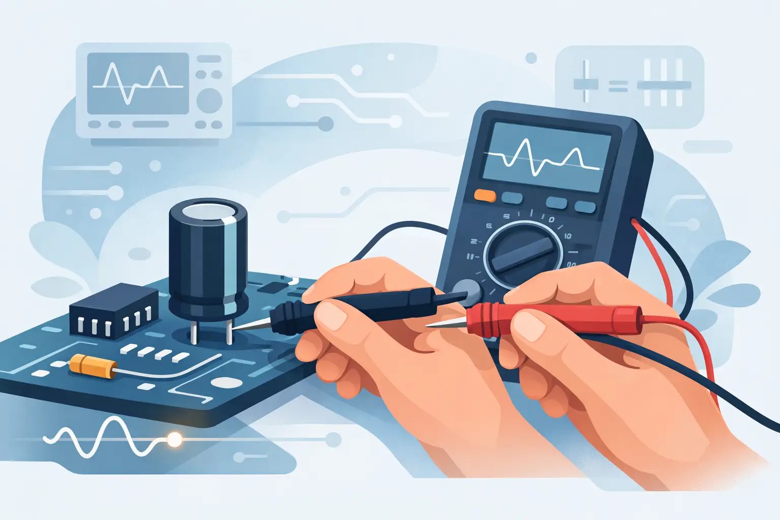
A capacitor can look perfectly normal and still cause a switching supply to pulse, an audio stage to distort, or a digital board to reset intermittently. The question of how to test capacitor in circuit comes up because removing every suspect component is slow, risky for multilayer boards, and impractical during production troubleshooting. An in-circuit measurement can quickly identify a likely failure, but it must be interpreted in the context of the surrounding circuit.
The central limitation is simple: a meter does not see only the capacitor. It sees every parallel path connected to it, including resistors, semiconductors, IC inputs, other capacitors, and power rails. A useful result requires the right test method, a discharged circuit, and an understanding of when one lead must be lifted for confirmation.
Start With Safety and Board State
Disconnect all power before measuring. Remove batteries where applicable, unplug external supplies, and wait for bulk capacitors to discharge. Do not assume a capacitor is safe because the equipment is switched off. High-voltage filter capacitors can retain a hazardous charge long after power removal.
Verify the voltage across the capacitor with a properly rated voltmeter before contacting it with tweezers or probes. If discharge is necessary, use an appropriate resistor and procedure for the circuit voltage and stored energy. Avoid shorting a charged capacitor directly with a screwdriver or test lead. That can damage the capacitor, board traces, and the tool, while creating an arc hazard.
Also consider what remains connected to the capacitor. A charged battery-backed rail, USB source, or adjacent power domain can energize the circuit even when the main supply is disconnected. In-circuit measurements are meaningful only when the device under test is genuinely unpowered.
Choose the Measurement That Matches the Failure
Capacitance alone does not tell the full story. A capacitor can measure near its marked value at a low test signal yet fail under ripple current, frequency, temperature, or bias voltage. For that reason, select the measurement based on the capacitor type and suspected fault.
For ceramic, film, and small surface-mount capacitors, capacitance is often the first useful screen. A reading far below the nominal value may indicate a cracked MLCC, an open connection, or a component that has been affected by DC bias. Remember that many high-value ceramic capacitors lose a substantial portion of their nominal capacitance under applied DC voltage. A low reading is not automatically a failed part unless it is compared with the design requirement and test conditions.
For aluminum electrolytic and polymer capacitors in power supplies, ESR is frequently more revealing. Elevated equivalent series resistance increases ripple voltage and heat generation. It can produce startup problems or unstable regulation even when a basic capacitance measurement appears acceptable. ESR testing is particularly valuable for locating aged output capacitors without desoldering every part.
Resistance or continuity mode has a different role. It is useful for finding a shorted capacitor or a severely leaky part, especially on a power rail. It is not a reliable way to verify capacitance value. A good capacitor typically causes the resistance reading to change as it charges from the meter’s test current, but the exact behavior depends heavily on meter design and the circuit around it.
How to Test a Capacitor in Circuit With an LCR Meter
An LCR meter with insulated tweezer probes is well suited to closely spaced SMD capacitors because it can contact both terminations directly. Position the tips on clean metal terminations, apply light and consistent pressure, and keep the contacts clear of neighboring pads. Poor contact resistance can create unstable readings, particularly when measuring low ESR or low capacitance.
First, identify the expected component value from the schematic, bill of materials, board marking, or comparison with an identical channel. Then measure capacitance and, where supported, ESR at a suitable test frequency. An automatic handheld instrument such as the LCR-Reader can identify the component type and select measurement parameters without requiring bench setup, which is useful when screening dense assemblies or comparing multiple locations quickly.
Treat the displayed value as a circuit-level result. If the measured capacitance is much higher than expected, another capacitor may be in parallel. If it is lower, a shunt resistor, semiconductor junction, or connected IC may be affecting the test signal. A reading that changes significantly when nearby circuitry is isolated is evidence that the original in-circuit value was influenced by the board rather than the capacitor alone.
For very small capacitors, lead and fixture effects matter. Keep probe spacing short, use clean tips, and perform the instrument’s recommended open and short calibration procedure when measurement accuracy is critical. At picofarad levels, residue, flux contamination, and finger contact can be enough to alter the reading.
Use ESR Results Carefully on Power Rails
ESR measurements are often effective in-circuit because a meter applies a small AC signal and evaluates the capacitor’s impedance behavior. However, parallel capacitors can make a poor capacitor appear better than it is. This is common on output rails containing several electrolytics, multiple ceramics, or a mixture of bulk and local decoupling capacitors.
Compare results among equivalent locations whenever possible. If one capacitor on a repeated channel shows substantially higher ESR than matching parts, it deserves attention. Compare against the capacitor’s series, voltage rating, capacitance, temperature rating, and intended use. A general-purpose electrolytic and a low-ESR switching-regulator capacitor do not have the same acceptable ESR range.
A very low ESR reading can also be misleading. It may indicate healthy parallel capacitance, but it can also result from a low-resistance path elsewhere on the rail. If a power rail is suspected of being shorted, use resistance or diode-mode checks and follow the rail rather than relying on ESR alone.
Check for Shorts and Leakage Without Misreading the Circuit
To screen for a shorted capacitor, measure resistance across the component after confirming the board is discharged. A stable near-zero resistance can indicate a short, but it may also be normal for a low-voltage power rail connected to ICs, regulators, or other capacitors. Compare the same rail to a known-good board or isolate sections of the rail before assigning fault to the capacitor.
A rising resistance value may suggest the capacitor is charging from the meter. That behavior is more meaningful on a simple, isolated circuit than on a populated board. Digital meters use different test currents and update rates, so do not diagnose leakage from the visual movement of one meter alone.
True leakage is best evaluated with a controlled DC voltage test near the capacitor’s operating voltage, using a current-limited supply or dedicated leakage tester. This is generally an out-of-circuit or partially isolated procedure. Applying a test voltage indiscriminately to an assembled board can damage low-voltage ICs and semiconductor junctions.
Know When to Lift One Lead
In-circuit testing is a screening and troubleshooting method, not a substitute for isolation in every case. Lift one lead, or remove the part, when the result conflicts with the symptom, when parallel paths are obvious, or when a precise capacitance and dissipation measurement is required.
Isolation is especially appropriate when verifying timing capacitors, high-accuracy analog filters, startup capacitors, and capacitors connected across semiconductor devices. It is also necessary when a board contains several capacitors in parallel and the goal is to identify the individual failed component rather than confirm a rail-level problem.
For SMD work, avoid excessive heat and pad stress. Use controlled hot air or a suitable soldering method, then allow the component to cool before measurement. Re-measure after isolation and compare the result with the rated tolerance at the meter’s test conditions.
Build a Faster Troubleshooting Sequence
Efficient capacitor diagnosis starts with the circuit symptom. On a switching supply, inspect output ripple and test ESR on the input and output capacitors. On a dead low-voltage rail, check for a short before replacing capacitors. On an intermittent board, inspect MLCCs near connectors, board edges, heat sources, and mechanically stressed areas for cracks or altered values.
Visual inspection remains useful, but it is not sufficient. Bulging, venting, electrolyte residue, discoloration, and lifted pads are clear warnings on electrolytics. Ceramic capacitors often fail without visible evidence. Their failures may appear only as a low resistance on a rail, a capacitance shift, or a fault that changes with board flexing or temperature.
The most reliable approach is to use the in-circuit reading to narrow the search, compare it with the circuit design and known-good locations, then isolate the component when the measurement cannot separate the capacitor from its parallel paths. That sequence saves rework while preserving the measurement confidence needed for professional repair and quality control.