
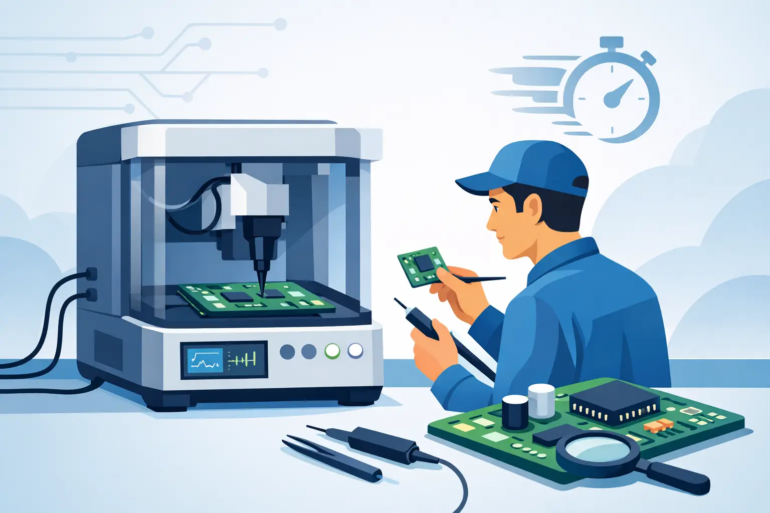
A failed board rarely announces which component caused the problem. A regulator rail is low, a signal is distorted, or a power supply is unstable, while dozens of nearly identical 0402, 0603, and 0805 parts remain soldered in place. An automatic SMD tester shortens the path from symptom to measurement by identifying the component under its probes and selecting an appropriate measurement mode without a sequence of menu selections.
For repair technicians, production personnel, and design engineers, that difference is practical rather than cosmetic. Conventional meters often require separate lead connections, function selection, range selection, and interpretation of readings that may be affected by the surrounding circuit. A tweezer-style automatic tester is built around the way surface-mount work actually happens: isolate the suspect part as far as the circuit allows, touch both terminations, and evaluate the displayed value.
What an Automatic SMD Tester Does
An automatic SMD tester is a handheld instrument designed to measure small surface-mount devices directly with tweezer probes. Depending on the model and the component, it can recognize and measure resistance, capacitance, inductance, and equivalent series resistance (ESR). Advanced instruments may also provide diode testing, manual test-frequency selection, continuity indication, data transfer, or extended measurement ranges.
The defining function is automatic component identification. When the probe tips contact an unknown two-terminal component, the instrument evaluates its electrical response and selects the most suitable measurement category and test conditions. This removes a common source of delays: switching from resistance to capacitance mode, then changing range or frequency because the initial reading does not make sense.
Automatic operation does not mean the technician should ignore measurement conditions. It means the instrument handles routine decisions quickly, so the operator can focus on whether a result is credible in the circuit and relevant to the fault.
Why Tweezer Measurement Changes SMT Troubleshooting
Surface-mount components are physically small, densely packed, and often installed near other electrically connected parts. Standard test leads can slip, bridge adjacent pads, or force the user to remove a component before obtaining even a basic result. Tweezer probes provide controlled contact at both ends of a chip resistor, capacitor, inductor, or diode.
This form factor matters most during fault isolation. A technician tracing a shorted power rail may need to compare several capacitors. A repair specialist diagnosing an intermittent device may need to check resistor values around a feedback network. An assembly operator may need to verify that an installed component matches the bill of materials before the board moves to the next station. In each case, speed comes from repeatable probe placement and immediate identification, not simply from a faster display refresh.
The best workflow is usually comparative. Measure a suspect part, then compare it with identical components in the same circuit area or with a known-good board. A reading that is slightly outside a nominal value may be normal when parallel paths are present. A component that reads dramatically different from its neighbors deserves closer investigation.
In-Circuit Readings Require Judgment
No handheld LCR meter can fully eliminate the effects of the circuit around a component. Parallel resistors reduce the apparent resistance. Multiple capacitors on a supply rail increase the apparent capacitance. Semiconductor junctions, IC inputs, and inductive paths can influence the result. An automatic tester gives a fast measurement, but it cannot determine circuit topology from two probe contacts.
That is why a good technician treats in-circuit measurement as evidence, not always final proof. If the reading is clearly abnormal, it may be enough to locate the failure. If the reading is close to the expected value but uncertainty remains, lift one end of the component or remove it and test it out of circuit. This trade-off is especially relevant for low-value resistors, high-capacitance rails, and components connected across active semiconductor circuitry.
Key Specifications to Evaluate Before Buying
An automatic SMD tester should be selected by the components and failure modes you encounter, not by automatic detection alone. Entry-level devices can be highly effective for common resistors, capacitors, and inductors. More advanced work may justify additional frequency control, lower ESR capability, diode testing, Bluetooth connectivity, or wider ranges.
| Specification | Why it matters in practical work | | — | — | | Resistance range and accuracy | Determines whether the tester can distinguish low-ohm current-sense resistors, common chip resistors, and high-value bias networks with useful confidence. | | Capacitance range and test frequency | Affects capacitor identification and helps evaluate components whose behavior changes with test conditions. | | ESR resolution | Useful for locating degraded capacitors, particularly in power circuits where capacitance alone may appear acceptable. | | Inductance range | Important for checking ferrite beads, chip inductors, and small power-stage inductors. | | Probe construction | Fine, durable, well-aligned tips improve access to small components and reduce accidental contact with adjacent pads. | | Calibration support | Provides traceability and confidence when measurements support quality decisions, repair documentation, or production verification. |
Accuracy specifications must be read with their test conditions. A headline accuracy figure may apply only within a defined range, frequency, signal level, and calibration state. For example, measuring a 1% resistor requires more than an instrument with a 1% basic accuracy claim. Probe contact resistance, pad oxidation, component tolerance, and in-circuit paths all contribute to the final result.
For quality-control use, calibration documentation and a suitable calibration fixture are part of the measurement system. A device that is accurate when new but never checked against a known standard is not a dependable basis for acceptance decisions.
A Fast, Repeatable Measurement Method
Start by inspecting the board. Look for cracked packages, discoloration, corrosion, missing parts, or solder bridges. Visual inspection often identifies defects that no meter reading will clarify, and it prevents probe tips from being placed on damaged pads that can produce misleading results.
Next, ensure the circuit is unpowered and discharged. Capacitors can retain energy after power is removed, and applying stored voltage to a sensitive meter input is avoidable equipment risk. Discharge high-energy capacitors through an appropriate method before testing. Do not rely on an automatic tester as a substitute for safe discharge procedures.
Clean probe tips and verify their condition. Oxidized or contaminated tips add unstable contact resistance, particularly when measuring low-value resistors or ESR. If your instrument supports zeroing or calibration verification, perform it according to the manufacturer’s procedure before critical work.
Place one tweezer tip on each component termination. Keep the tips stable, avoid contacting neighboring pads, and wait for the reading to settle. For unknown parts, record both the identified type and the measured value. A component marked as a resistor but identified as a capacitor, diode, or unstable open circuit may indicate that the probes are contacting a network rather than the intended part, or that the component has failed.
When results are questionable, compare like with like. Measure the same reference position on a known-good board, or compare several nominally identical components on the same board. This is often more useful than relying solely on printed markings, which are absent on many small SMD components.
Common Mistakes That Waste Troubleshooting Time
The first mistake is assuming every in-circuit reading represents the component alone. A 10 kOhm resistor can read lower because another resistance path is in parallel. A ceramic capacitor can appear shorted on a rail because the rail feeds a damaged IC. Removal may be necessary before assigning blame.
The second is testing while the board is energized or partially energized. Even when the meter survives, external circuit voltage can distort readings and lead to incorrect conclusions. Power-off testing and discharge should be the default for passive component measurement.
The third is overlooking probe pressure and alignment. Excessive pressure can skid a tip across pads or damage a delicate part. Too little pressure produces inconsistent contact. Fine SMD work rewards a steady hand and clean tips more than force.
Finally, avoid selecting a tester solely because it is automatic. Automatic identification is valuable, but range, accuracy, ESR performance, frequency options, calibration support, and ergonomic probe design determine whether the instrument will remain useful as your work changes.
Matching the Tester to the Job
For field repair and general bench work, a compact automatic tweezer meter that measures resistance, capacitance, inductance, and ESR may be the most efficient choice. It reduces setup time and fits naturally beside a microscope, hot-air station, and soldering iron.
For production verification, component sorting, or documented quality processes, prioritize repeatability, calibration capability, and clear specifications. For advanced diagnostics, manual control over test frequency and access to diode or extended-range functions can justify a higher-tier instrument. LCR-Reader instruments are designed around this progression, from straightforward automatic SMD measurement to professional models with expanded control and connectivity.
The right automatic SMD tester does not replace circuit knowledge. It gives that knowledge faster, cleaner measurements at the component level. Keep the probes clean, question readings that conflict with the circuit, and use comparison measurements whenever a board leaves room for doubt.