
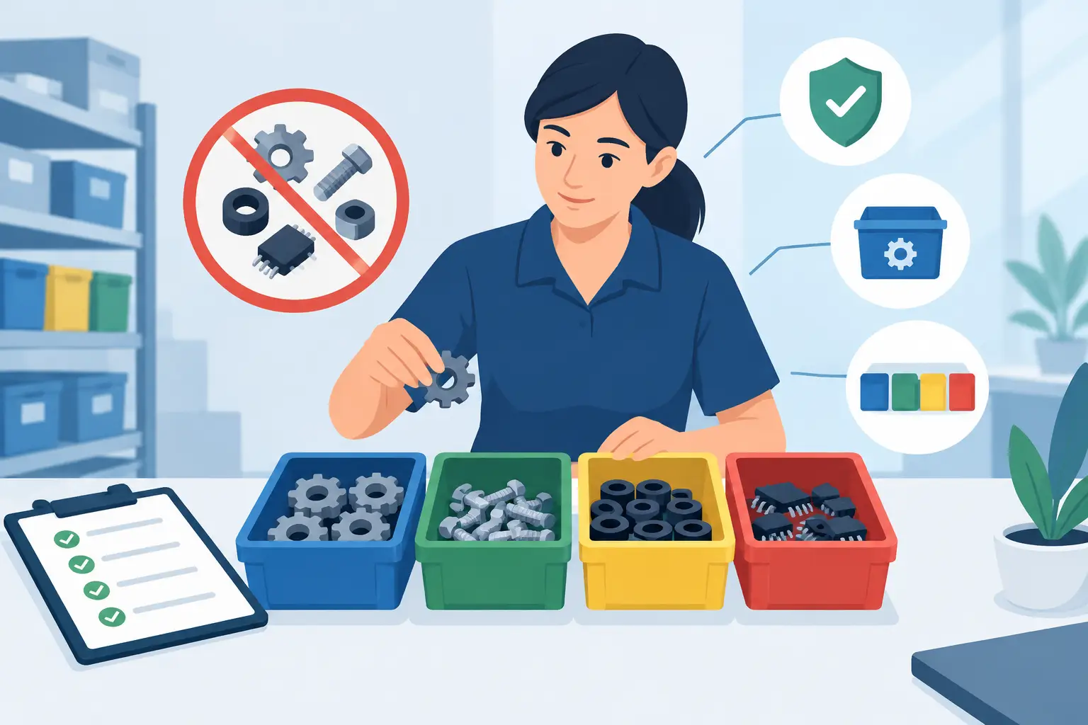
A 10 kΩ resistor and a 100 kΩ resistor can look identical in an 0402 reel. A 1 µF MLCC may share the same package and marking behavior as a nearby 100 nF part. These are not minor inventory errors when they reach a board: they can cause failed functional tests, unstable analog circuits, incorrect timing, and expensive rework. The most reliable ways to prevent component mixups combine physical control, documented identification, and direct electrical verification.
1. Treat Incoming Parts as Unverified Until Checked
A supplier label is useful, but it should not be the only source of truth. Receiving errors, substituted reels, incorrect purchase-order entries, and manufacturer packaging changes can all introduce risk before a component reaches production or a repair bench.
For high-risk parts, verify the received reel or bag against the purchase order, manufacturer part number, package size, value, tolerance, voltage rating, and lot information. Record the check before the material is placed into stock. This is especially valuable for components with identical footprints but different electrical behavior, such as capacitors with different dielectrics, MOSFETs with different pinouts, and inductors with similar markings.
Electrical spot checks add another layer of control. Measure a representative sample from a new reel before releasing it to production. A sample check will not detect every labeling error, but it can catch a reel that is fundamentally wrong before hundreds of placements are made.
2. Use Labels That Identify More Than the Value
A handwritten label that says “10K” is not enough when several 10 kΩ resistors exist in stock. A complete working label should identify the part number, nominal value, package, tolerance, and, where relevant, voltage rating, temperature coefficient, dielectric, or power rating.
For example, “10 kΩ, 1%, 0402, 0.063 W” is far more actionable than “10K.” For capacitors, include the capacitance, voltage rating, package, and dielectric when it matters to circuit performance. “1 µF, 16 V, X7R, 0603” prevents confusion with an otherwise similar 1 µF Y5V or C0G part.
Keep the manufacturer reel label attached whenever possible. If material must be moved into a bin, cut tape, or temporary container, transfer the full identification immediately. Do not rely on memory or on a label that will be separated from the parts after the next job.
3. Separate Similar Components Physically
Physical separation is one of the simplest controls because it reduces the chance of selecting the wrong part under normal bench pressure. Adjacent storage locations should not contain easily confused values, package sizes, or polarity-sensitive components without a clear visual distinction.
Use dedicated bins, labeled reel racks, or component drawers with one internal part number per location. If a bin must hold multiple lots, they should still be the same approved manufacturer part number or be explicitly approved alternates. Mixing equivalent-looking parts in the same unmarked container may save space, but it transfers risk directly to assembly and troubleshooting.
For active repair work, keep only the parts required for the current board or task on the bench. Return unused components to their identified containers before beginning another repair. Small loose piles are a common source of mixups, particularly with 0201, 0402, and 0603 devices.
4. Control One Open Reel or Cut Tape at a Time
Component mixups often occur during changeovers rather than during normal placement. Two open reels of similar resistors, two strips of SOT-23 transistors, or several loose cut tapes can quickly become indistinguishable once their labels are removed or folded under.
Open one reel or cut tape at a time for each feeder, placement station, or repair task. Keep the original label visible, and attach a secondary label to the free end of cut tape if the material will be handled away from the reel. When a reel is removed from a feeder, identify the feeder position and verify that the replacement part matches the setup record.
This discipline may feel slow for low-volume work. In practice, the few seconds spent controlling open material are far less costly than tracing an intermittent fault caused by one incorrect capacitor or resistor array.
5. Verify Parts by Measurement When Appearance Is Not Enough
Visual inspection cannot reliably distinguish unmarked surface-mount resistors, capacitors, inductors, and many diodes. When the electrical value is critical, measurement should be part of the workflow rather than a last resort.
A tweezer-style LCR meter is particularly useful for loose SMT components because it can contact both terminations directly without fixture setup. An instrument such as the LCR-Reader can automatically identify resistance, capacitance, or inductance and select appropriate test conditions, allowing a technician to confirm a part before placement or replacement.
Measurement must be interpreted correctly. Capacitance can vary with DC bias, test frequency, temperature, and dielectric type. Inductance readings can be influenced by test conditions and component construction. Low-resistance values require good probe contact and attention to lead or contact resistance. For critical parts, compare the measured result against the component specification and the expected tolerance at the applicable test condition.
Do not assume an in-circuit measurement identifies an individual component. Parallel paths, semiconductor junctions, and nearby components can distort the reading. When a reading is questionable, lift one end of the component or measure a known loose sample.
6. Match the BOM, Placement Data, and Board Reference Designators
A bill of materials should be more than a purchasing document. It is the primary reference for connecting a designator, an approved component, and its electrical requirements. Every assembly and repair process should use a controlled BOM revision and placement reference.
Before loading parts or beginning rework, verify that the board revision, BOM revision, and assembly drawing agree. A component that was correct for an earlier revision may be incorrect for the board on the bench. This is common when resistor values, capacitor voltage ratings, pull-up networks, or transistor footprints change between revisions.
For manual assembly, organize components in reference-designator order or by a clearly documented placement sequence. For repair, compare the suspected component’s reference designator with the schematic, BOM, and known-good board data before removing it. The value alone may not tell the whole story, particularly where multiple approved alternates or application-specific variants exist.
7. Build Verification Into Rework, Not Just Production
Rework is a high-risk environment because technicians often work from partial information. A failed board may contain previous repair attempts, damaged markings, or components moved from another location. The correct replacement is not always the part that looks most similar.
Before installing a replacement, confirm the reference designator, package, orientation, value, rating, and function in the circuit. For polarized components, verify the board polarity marking against the actual device pinout. For transistors, regulators, and diodes, confirm the pin configuration from the approved device documentation. Two SOT-23 devices can have the same body style and entirely different pin assignments.
After placement, inspect the part and measure where practical. A quick resistance, capacitance, diode, or continuity check can reveal a wrong component, solder bridge, or open joint before power is applied. This is particularly effective for passive replacements and for troubleshooting dense SMT assemblies.
8. Use Traceability for Parts That Affect Reliability or Compliance
Not every resistor used in a prototype needs lot-level documentation. But for production boards, safety-related assemblies, medical, industrial, aerospace, or high-reliability work, traceability should be matched to the consequences of a mixup.
At minimum, retain the approved part number, supplier, lot or date code when available, receiving record, and board build record. For controlled processes, record who performed verification and what instrument or method was used. Calibration status matters when measurements are used as acceptance evidence rather than informal troubleshooting data.
The trade-off is administrative effort. The right level of traceability depends on production volume, failure cost, regulatory requirements, and the component’s role in the design. Apply the tightest controls to parts that are visually similar, difficult to inspect after assembly, or capable of creating a safety, compliance, or field-reliability issue.
A component-control process works best when it is easy to follow at the point of use. Clear labels, separated storage, controlled open material, and a fast measurement check turn identification from a memory test into a repeatable engineering procedure. That is how a bench or production line stays fast without accepting avoidable uncertainty.