
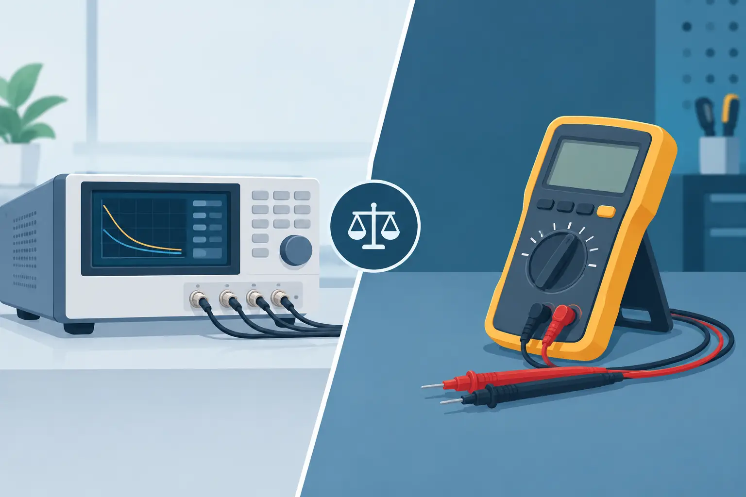
A 0402 capacitor that reads incorrectly can waste more troubleshooting time than a failed IC. That is where the choice between automatic versus manual LCR meters becomes practical rather than theoretical. The right instrument depends on whether the immediate job is identifying an unknown part at the board, characterizing a component under defined conditions, or documenting repeatable measurements for quality control.
Automatic and manual LCR meters measure the same basic component properties: resistance, capacitance, inductance, and often ESR. Their difference is workflow. An automatic meter is designed to recognize the connected component and select a suitable measurement function with minimal operator input. A manual meter gives the user direct control over settings such as test frequency, equivalent circuit model, test level, and measurement speed.
For SMT repair, incoming inspection, and component sorting, removing setup steps can matter as much as adding measurement functions.
What an Automatic LCR Meter Does Differently
An automatic LCR meter evaluates the impedance behavior of the part under test, identifies the most likely component category, and presents the relevant result. With a tweezer-style instrument, the process can be as direct as touching both terminals of a surface-mount part. The meter determines whether the component behaves primarily as a resistor, capacitor, or inductor, then applies appropriate test conditions from its internal measurement logic.
This approach is especially useful when the component marking is absent, too small to read, or unreliable. It also reduces a common bench error: measuring a capacitor using a resistance mode, or accepting a misleading capacitance result from a resistor in a circuit path.
Automatic selection is not the same as guessing. A properly designed automatic instrument uses measured electrical response to classify the component. The result is a faster path to a usable value, particularly for common passive components encountered during repair and assembly work.
The operational advantage is clear when technicians measure dozens of components in a shift. There is no need to stop, enter a menu, choose a range, select a test frequency, and then reposition the probes. For small discrete parts, that sequence can take longer than the measurement itself.
Where automatic measurement saves the most time
Automatic operation is most valuable when the component type is unknown or when measurement conditions do not need to be manually fixed for every part. Typical examples include board-level troubleshooting, identifying loose reel samples, verifying parts removed from a PCB, and sorting mixed passives after rework.
It also benefits field service and mobile repair. A handheld meter that is ready when it touches the component is more likely to be used consistently than a more complex instrument that requires setup before every reading.
For these applications, repeatable handling matters. Tweezer probes provide a short measurement path and allow controlled contact with both ends of an SMT device. This helps reduce the practical difficulties of holding tiny parts with leads, clips, or conventional probes.
Manual LCR Meters Provide Defined Test Conditions
A manual LCR meter is the better choice when the test condition itself is part of the engineering question. Capacitance and inductance are not always fixed, single-number properties. They can vary with frequency, AC test level, DC bias, temperature, and the component’s construction. ESR and dissipation factor can also be frequency-dependent.
Manual control lets the operator specify those conditions instead of accepting the meter’s default selection. An engineer comparing capacitor behavior at 100 Hz, 1 kHz, and 10 kHz needs that control. So does a quality process built around a documented test procedure with defined limits and a specified equivalent circuit.
The primary trade-off is operator time. More settings create more ways to tailor a measurement, but also more ways to choose an unsuitable setting. A reading can be technically precise while still being irrelevant if the frequency, circuit model, or fixture is wrong for the component and the intended application.
Settings that matter in manual LCR measurement
Manual instruments commonly allow control of several variables. Test frequency affects reactive components most visibly. A ceramic capacitor, electrolytic capacitor, power inductor, and RF inductor may need very different frequencies for meaningful evaluation.
The equivalent circuit model is also significant. Series and parallel representations describe losses differently. A low-impedance component may be better evaluated in series mode, while a high-impedance component may be more appropriate for a parallel model. The correct choice depends on the part’s impedance and the test standard or design requirement.
Test signal level can matter with nonlinear parts. Some inductors, ferrites, and semiconductor-adjacent circuits may respond differently as stimulus changes. Manual control makes those effects visible, but it requires the user to understand why the settings were selected.
Automatic Versus Manual LCR Meters by Application
The most useful comparison is not which category is universally better. It is which workflow places the greatest value on speed or parameter control.
| Application | Automatic LCR Meter | Manual LCR Meter | |—|—|—| | SMT troubleshooting | Excellent for rapid in-circuit checks and removed-part identification | Useful when a suspect part needs evaluation at a defined frequency | | Component sorting | Fast for mixed parts and unmarked passives | Better when sorting must follow controlled acceptance limits | | Production inspection | Effective for quick verification and rework stations | Preferred for formal procedures with prescribed test parameters | | Design characterization | Useful for quick baseline readings | Preferred for frequency sweeps, circuit-model selection, and detailed analysis | | Field repair | Highly practical because setup is minimal | Practical only when the work justifies added setup time |
A repair technician generally benefits more from automatic identification than from manual frequency selection on every measurement. A design engineer validating a capacitor for a switching supply may need exactly the opposite: controlled frequency, known fixture effects, and documented conditions.
Accuracy Is More Than the Displayed Resolution
An LCR meter can display many digits without delivering a meaningful measurement. Accuracy depends on the instrument’s specified uncertainty, calibration condition, test frequency, fixture quality, contact resistance, and the way the component is connected.
For low-value resistors and low-ESR capacitors, probe and contact resistance can become a significant part of the reading. For very small capacitance and inductance values, stray capacitance and lead inductance can dominate. This is why short test paths, stable contacts, and appropriate calibration or compensation procedures matter.
A tweezer-style meter has a practical advantage for small SMT components because the probe geometry minimizes unnecessary lead length. However, no handheld instrument can eliminate all measurement limitations. Oxidized terminals, flux residue, damaged pads, parallel circuit paths, and poor probe pressure can still distort the result.
Manual meters can offer more opportunities to compensate for a fixture, select a measurement range, or control the test setup. Automatic meters reduce handling variables by simplifying the measurement process. The best choice depends on which source of error is more likely in the actual workflow: inconsistent operator setup or insufficient control over the test condition.
In-Circuit Measurement Requires Judgment
Neither automatic nor manual LCR measurement should be treated as a guarantee that an in-circuit reading represents the isolated component value. Parallel components, semiconductor junctions, power rails, and connected ICs can alter the measured impedance. A capacitor across a supply rail may read much higher than expected because the meter is also seeing surrounding circuitry. A resistor can appear lower because of parallel paths.
Automatic classification remains helpful because it quickly shows how the node behaves electrically. But when the reading is questionable, compare it with a known-good board, consult the circuit, or lift one end of the component when practical. This is often faster than repeatedly changing meter modes in search of a number that looks right.
For board work, the ideal instrument is one that delivers a quick first answer and lets the technician decide when deeper verification is necessary. LCR-Reader tweezer-style instruments are designed around that workflow: direct contact, automatic component recognition, and portable measurement where the component is located.
Choosing the Right Meter for the Bench
Choose an automatic LCR meter if most measurements involve unknown, small, or high-volume passive components. It is the efficient option for repair benches, rework stations, field technicians, and users who need a dependable answer without a setup sequence. Automatic operation is also a strong fit for technicians who measure a wide range of parts but do not need to define a separate test frequency for each one.
Choose a manual LCR meter if measurement settings must be controlled, recorded, and repeated as part of an engineering or quality process. It is the stronger tool for component characterization, specification verification, and applications where test frequency and equivalent circuit selection materially affect pass or fail decisions.
Many professional benches benefit from both approaches. An automatic handheld meter handles rapid identification and immediate troubleshooting. A manual instrument supports deeper analysis when a component must be evaluated against a defined requirement.
The useful question is not whether automatic operation replaces engineering judgment. It is whether your meter removes unnecessary setup from the measurements you perform most often. For a technician facing a board full of unmarked passives, the fastest correct measurement is usually the one that keeps the repair moving.