
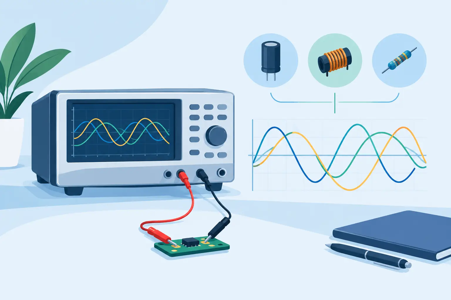
A 10 uF ceramic capacitor can appear close to its marked value at one test frequency and substantially lower at another. A small inductor may look acceptable at low frequency but show rising loss as frequency approaches its self-resonant region. That is why selecting LCR test frequency is not a minor meter setting. It determines which electrical behavior of the component is being measured.
For repair, incoming inspection, and SMT troubleshooting, the correct frequency depends on the component type, its intended operating conditions, and whether it is measured in or out of circuit. The goal is not simply to obtain a stable number. The goal is to obtain a number that represents the parameter needed for a sound engineering decision.
Why Test Frequency Changes an LCR Reading
Real components are not ideal R, L, or C elements. Every capacitor has equivalent series resistance (ESR), equivalent series inductance (ESL), dielectric loss, and leakage. Inductors have winding resistance, core loss, distributed capacitance, and a self-resonant frequency. Even resistors may display parasitic inductance or capacitance at higher frequencies.
An LCR meter applies an AC test signal and calculates impedance, phase angle, and related parameters. Changing the signal frequency changes the impedance of reactive elements. Capacitive reactance falls as frequency rises, while inductive reactance rises. Loss mechanisms can also change significantly across the frequency range.
This means a reading is incomplete without its test conditions. A capacitance value measured at 100 Hz and one measured at 100 kHz may both be valid, but they may answer different questions. For component verification, the most useful setting is normally the frequency specified on the part data sheet. For troubleshooting, the best setting is often the one that most clearly separates a good component from a suspect one.
Selecting LCR Test Frequency by Component Type
Capacitors: Follow Dielectric Behavior and Data-Sheet Conditions
Capacitor test frequency is strongly dependent on dielectric type and capacitance value. Larger electrolytic capacitors are commonly specified at relatively low frequencies, such as 100 Hz or 120 Hz. At these frequencies, the measurement better reflects the capacitor behavior relevant to low-frequency filtering and bulk energy storage.
Small ceramic capacitors are commonly characterized at higher frequencies, often 1 kHz, 10 kHz, or higher depending on capacitance and the manufacturer’s specification. High-K ceramic dielectrics can show capacitance variation with frequency, DC bias, temperature, and aging. A reading that differs from the nominal marking is not automatically evidence of failure unless the test method matches the specified conditions.
Film capacitors tend to remain more stable over frequency than high-K ceramics or electrolytics, but their data sheets still define the reference test conditions. Use those conditions for inspection or quality-control work. If a data sheet states capacitance tolerance at 1 kHz, measuring at 100 Hz may create an avoidable discrepancy.
ESR requires particular care. ESR is frequency-dependent, and a low-frequency ESR result should not be treated as a direct substitute for ESR at a switching regulator’s operating frequency. When diagnosing a power supply, test frequency should be chosen with the circuit function in mind. A capacitor used in a high-frequency converter must be evaluated for low loss in the frequency region where the converter stresses it.
Inductors: Stay Below Self-Resonance
Inductance measurements become less representative as the test frequency approaches the component’s self-resonant frequency (SRF). Below SRF, an inductor behaves primarily as an inductive element. Near resonance, distributed capacitance interacts with inductance, phase angle shifts, and the reported value can become unstable or misleading. Above SRF, the component may behave capacitively.
For a power inductor, choose a frequency that is low enough to remain well below SRF and, where possible, aligns with the manufacturer’s specified test frequency. Many inductors are specified at 100 kHz or 1 MHz, but this varies greatly by inductance value, construction, and intended application. A small RF inductor may be characterized at a much higher frequency than a shielded power inductor.
Also distinguish between verifying nominal inductance and evaluating operating loss. A low-level LCR test signal does not reproduce the DC current, core bias, or temperature that a power inductor experiences in service. It remains useful for identifying wrong values, open windings, cracked terminations, and gross parameter shifts, but it is not a full load test.
Resistors: Use Frequency to Reveal Parasitics When Needed
For ordinary resistors measured at low frequency, test frequency usually has little effect on resistance. This is why automatic handheld instruments can identify and measure common chip resistors quickly and reliably.
At higher frequencies, resistor construction matters. Wirewound parts can show inductive behavior. Thick-film and thin-film components may exhibit different parasitic effects. In RF circuits, a resistance value alone may not describe how the part behaves. If the objective is basic value verification, use a conventional low or midrange test frequency. If the objective is high-frequency fault analysis, examine impedance and phase behavior at a frequency relevant to the circuit.
Match the Frequency to the Measurement Objective
The same component may need different test frequencies for different work. This is common in production, repair, and design validation.
For incoming inspection, use the manufacturer’s data-sheet frequency and test level whenever possible. This gives a defensible pass/fail comparison. Record the frequency with the measured value, especially for capacitors and inductors.
For board-level troubleshooting, start with a frequency appropriate to the expected component type and nominal value. Then compare the suspect location with an identical component on a known-good board, if one is available. Comparative measurements are often more valuable than relying only on nominal values because in-circuit paths, parallel parts, and semiconductor junctions can affect the result.
For functional diagnosis, choose a frequency related to the circuit’s role. Low-frequency filter capacitors, switching converter capacitors, RF matching inductors, and timing components do not need the same measurement conditions. The selected frequency should help reveal the failure mode that matters, not merely produce the closest nominal value.
In-Circuit Measurement Adds Another Variable
Test frequency cannot eliminate all in-circuit measurement errors. Parallel components can increase apparent capacitance or decrease apparent resistance. Semiconductor paths can affect readings. Nearby inductors, capacitors, and traces can introduce alternate current paths that do not exist when the component is isolated.
Frequency can sometimes help separate these effects. A low test frequency may emphasize leakage paths or large parallel capacitance. A higher frequency may make a small capacitor easier to identify, although it can also introduce more influence from board parasitics. There is no universal setting for populated boards.
Use the following practical sequence when a reading is questionable: measure the component at the data-sheet frequency, compare it with a known-good location, try a second appropriate frequency, and isolate one terminal if the circuit path still makes the result ambiguous. This approach is faster than repeatedly changing settings without a measurement hypothesis.
Automatic Versus Manual Frequency Selection
Automatic parameter selection is valuable when speed matters. A handheld tweezer-style meter can identify a component and apply suitable measurement conditions without menu navigation, making it practical to inspect dense SMT boards one part at a time. For routine resistor, capacitor, and inductor checks, this reduces setup time and operator error.
Manual frequency selection becomes more useful when the measurement must match a data sheet, process requirement, or suspected failure mechanism. It is also useful when comparing readings between instruments or documenting quality-control results. An instrument with selectable frequency gives the technician a way to move from a fast screening measurement to a controlled verification measurement.
LCR-Reader instruments are designed for the first part of that workflow: fast, direct component identification with tweezer contact. For advanced work, the right instrument is one that provides the frequency options, accuracy, calibration status, and connection method required by the job rather than features that add unnecessary setup.
Test Signal Level, Calibration, and Connection Quality
Frequency is only one test condition. Test voltage or current can affect voltage-sensitive capacitors, magnetic components, and semiconductor-adjacent circuit paths. A low signal level may be preferred for sensitive in-circuit work, while a specified level may be needed to reproduce a data-sheet result.
Calibration and fixture compensation also matter more as component values get smaller. Residual lead inductance, contact resistance, and stray capacitance can distort results, particularly at higher frequencies. Keep tweezer tips clean, use stable contact pressure, and perform the instrument’s recommended calibration or compensation procedure with the intended fixture or probe setup.
For very low resistance, Kelvin connections can reduce errors caused by lead and contact resistance. For very small capacitance or inductance, minimize lead length and keep the measurement environment consistent. A technically correct frequency cannot compensate for poor connections or uncorrected fixture effects.
The most useful LCR reading is one you can explain: the component was measured at a known frequency, with appropriate signal conditions, calibrated contacts, and a clear comparison target. Start with the data sheet when verifying parts, then adjust frequency deliberately when troubleshooting requires a closer look at real circuit behavior.