
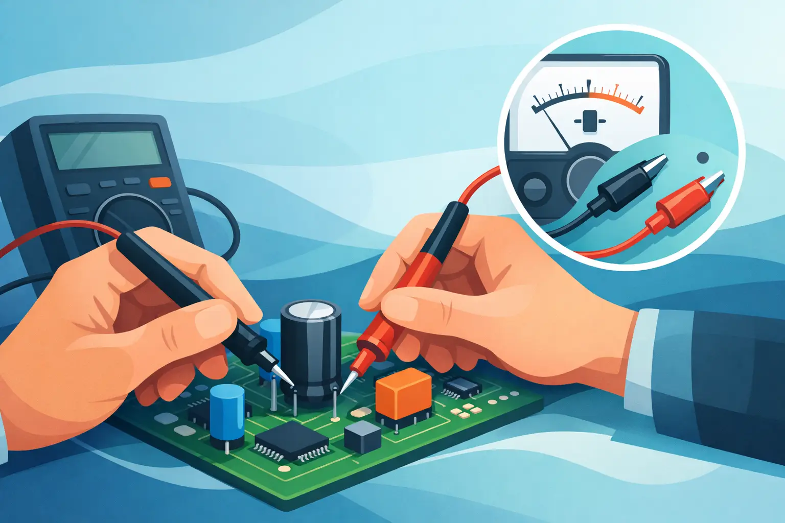
A capacitor can look perfect and still be the reason a power rail will not start, an audio channel hums, or an SMT board resets under load. The ability to measure a capacitor without desoldering can cut fault-isolation time dramatically, but an in-circuit number is only useful when you understand what the rest of the circuit is contributing.
The short answer is yes: you can often check capacitance, ESR, leakage symptoms, and shorts with the capacitor still on the PCB. The more useful answer is that measurement confidence depends on the capacitor type, the circuit topology, the test frequency, and whether other components create a parallel path. A handheld LCR or ESR meter with tweezer probes is particularly effective for small SMD parts because it measures directly at the component terminations with minimal handling.
What an In-Circuit Capacitor Measurement Really Shows
When probes touch a capacitor installed on a board, the meter does not see only the capacitor. It sees the total impedance between those two nodes. Any resistor, semiconductor junction, IC input, inductor, or second capacitor connected across the same points can affect the reading.
For capacitance, parallel capacitors add together. A 10 uF capacitor connected across a rail with several other bypass capacitors may appear much larger than its marked value. A resistor in parallel can prevent some meters from settling or cause the instrument to identify a mixed impedance rather than a clean capacitance value.
ESR testing often provides a more practical in-circuit result, especially when diagnosing electrolytic capacitors in power supplies. A meter applies a small AC test signal and evaluates the capacitor’s equivalent series resistance. In many circuits, surrounding parts have less effect on ESR than they do on low-frequency capacitance. That is not a guarantee, however. Low-resistance traces, parallel capacitors, switching devices, or transformer windings can still produce misleading values.
The goal is not to treat every in-circuit reading as a final certification. The goal is to identify clear failures quickly and reserve desoldering for measurements where the circuit makes the result ambiguous.
Prepare the Board Before You Test
Never begin by placing an LCR meter across a powered circuit. Remove all power sources, disconnect batteries where possible, and wait for supply capacitors to discharge. High-voltage equipment requires an appropriate discharge procedure and verified safe voltage before any measurement begins.
Use a DMM to confirm that voltage across the capacitor is near zero. Do not intentionally short a charged capacitor with a screwdriver or probe tip. That can damage the capacitor, PCB traces, nearby semiconductors, and the tool. For larger capacitors, discharge through a suitable resistor rated for the expected voltage and stored energy.
Also consider the state of the circuit. A capacitor connected to a regulator output may remain tied to other charged rails through protection diodes or IC structures. A board that appears off can still retain voltage in several locations. Confirm the actual nodes being tested, not just the condition of the power switch.
How to Measure a Capacitor Without Desoldering
Start with a visual check. Look for electrolyte residue, a raised vent, a cracked MLCC, heat discoloration, or damaged solder joints. Visual evidence does not replace measurement, but it directs attention to parts that deserve immediate verification.
With the board unpowered and discharged, place the probe tips directly on the capacitor terminals. For SMD components, tweezer-style probes provide stable contact and reduce the error caused by leads, clips, and hand movement. Keep the tips clean, use light pressure, and avoid bridging adjacent pads.
An automatic LCR meter can identify whether the measured impedance behaves primarily as capacitance, resistance, or inductance, then select an appropriate measurement mode. Record the displayed capacitance and ESR, but interpret both against the component marking, schematic value, location in the circuit, and known-good channels when available.
If a reading is clearly abnormal, the component may be defective even in circuit. Examples include a capacitor reading as a near short, an electrolytic showing substantially elevated ESR compared with an equivalent known-good part, or an MLCC on a supply rail showing a resistance-like low impedance that persists after the rail is isolated.
If the reading is merely somewhat high or low, do not assume failure. Parallel parts and circuit loading are common reasons for a plausible but incorrect measurement.
Read Capacitance as a Screening Value
Capacitance is easiest to interpret when the capacitor is relatively isolated. Small timing capacitors, coupling capacitors, and parts on one side of a disconnected circuit path can sometimes be measured accurately enough in place.
Power-rail capacitors are different. Multiple capacitors are normally connected in parallel to lower impedance across a broad frequency range. Measuring one 1 uF ceramic capacitor in a bank may show the value of the entire bank, not the individual part. If the meter reports 8 uF, that may be correct for the nodes being tested and still tell you nothing about the selected 1 uF component.
Ceramic capacitors add another complication: many high-value MLCCs lose capacitance under DC bias. A removed part measured at a small test voltage can meet its nominal value, while the same part in operation has considerably less effective capacitance. In-circuit measurement will not fully characterize that bias behavior.
Use ESR to Find Aging Electrolytics
ESR is often the faster diagnostic measurement for aluminum electrolytic capacitors. As an electrolytic dries out or deteriorates, its capacitance can remain close to nominal while ESR rises enough to cause ripple, poor startup, overheating, or unstable regulation.
Compare ESR against the capacitor’s type, capacitance, voltage rating, application, and temperature rating. There is no single acceptable ESR value for every 100 uF or 1000 uF capacitor. A low-impedance switching-supply capacitor is expected to have much lower ESR than a general-purpose capacitor of the same capacitance.
In-circuit ESR results are strongest when one capacitor is the dominant path across a node. They become less decisive when several capacitors share the rail. A low ESR result in a parallel bank may simply reflect the combined effect of the remaining good capacitors, masking one degraded part.
Know When One Lead Must Be Lifted
Desoldering is not always necessary, but lifting one capacitor lead or removing one SMD termination is the correct next step when the decision matters and the in-circuit result is uncertain. Isolating one terminal breaks most parallel paths without requiring full component removal.
Consider isolation when the measured capacitance is higher than the marked value, when identical channels disagree but neither reading is clearly failed, or when a capacitor is part of a dense decoupling network. Isolation is also necessary for accurate leakage testing because the surrounding circuit may provide alternate current paths.
For multilayer ceramic capacitors suspected of a short, full removal may be more efficient than repeated in-circuit measurements. A shorted MLCC on a low-voltage rail can be difficult to identify because every capacitor on that rail measures across the same low-resistance node. Thermal methods, controlled current injection, or sectional isolation may be needed before component-level confirmation.
Reduce Measurement Error at the Bench
Instrument setup still matters, even with automatic meters. Calibrate or compensate the probe fixture as specified by the instrument manufacturer, especially when measuring low capacitance, low ESR, or small SMD components. Contamination on probe tips and oxidation on pads can add contact resistance and create unstable readings.
Use the appropriate test frequency when your instrument offers manual selection. A capacitor’s impedance changes with frequency, and ESR behavior can vary significantly between low-frequency capacitance testing and higher-frequency switching-supply evaluation. Measurements should be compared at the same test conditions whenever possible.
For repeatable troubleshooting, record the component designation, displayed value, test frequency, and board condition. Comparing a suspect board against a known-good board under the same conditions is often more valuable than comparing one reading to a generic online reference. This is particularly true for proprietary equipment, where circuit loading may be intentional.
A compact instrument such as the LCR-Reader is designed for this workflow: direct contact at SMT terminals, automatic component identification, and rapid checks without the lead inductance and setup time of conventional clip-based measurements. It helps establish whether a component deserves deeper investigation, but it does not override the electrical reality of parallel circuit paths.
Make the Reading Answer the Right Question
The practical question is rarely, “Is this capacitor exactly its labeled value?” More often it is, “Is this component clearly shorted, open, high-ESR, cracked, or inconsistent with a known-good circuit?” In-circuit measurement is exceptionally effective for those first-pass decisions.
Treat a clear failure as actionable, treat a clean result in a heavily parallel network as provisional, and isolate the part when accuracy will determine the repair. That approach keeps troubleshooting fast without giving a convenient in-circuit reading more authority than it has earned.