
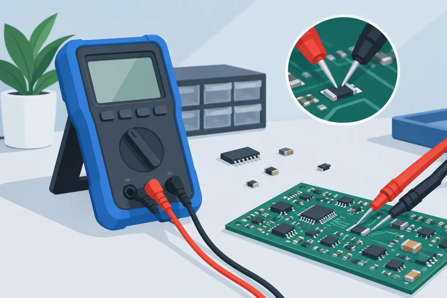
A 0402 capacitor that looks identical to its neighbors can stop an entire board from powering up. The useful handheld LCR comparison is not the one that simply lists measurement ranges. It is the one that shows how quickly an instrument can identify that part, how trustworthy the reading is at the required test conditions, and whether the probe can reach the component without disturbing the circuit.
For SMT repair, incoming inspection, and component sorting, the meter is part of the workflow. A handheld instrument that requires lead changes, function selection, or repeated range adjustments can be accurate and still cost valuable bench time. The right choice depends on the components being tested, whether measurements are made in or out of circuit, and how much control the job requires.
What a Handheld LCR Comparison Should Answer
A practical comparison starts with the job, not the feature list. A technician checking loose reels of capacitors has different needs from an engineer diagnosing a power rail with low-ESR polymer capacitors. Likewise, a field technician may prioritize pocketable size and automatic operation, while a lab user may need selectable test frequency and detailed manual control.
Three questions narrow the selection quickly. First, does the instrument automatically identify resistance, capacitance, inductance, and diode behavior? Second, can it measure the values and loss characteristics that matter for the components on the board? Third, can its probes make consistent contact with small packages without adding excessive handling time?
A conventional handheld LCR meter with test leads can be appropriate for through-hole parts, larger inductors, and occasional verification. For dense SMT work, tweezer-style instruments have a clear mechanical advantage: the operator can grasp a component directly and obtain a reading without swapping leads or trying to hold probes in place.
Handheld LCR Comparison: Measurement Performance
Measurement performance is more than the largest value printed in a specification table. Resolution, basic accuracy, test frequency, test voltage, and the method used to select measurement parameters all affect whether a displayed result is useful.
Automatic identification and range selection
Automatic component recognition is one of the most meaningful differences between handheld tools. It reduces setup decisions by determining whether the item under test behaves as a resistor, capacitor, inductor, or diode, then selecting a suitable measurement mode and range.
That convenience is especially valuable when sorting mixed components or investigating a board with uncertain markings. Automatic operation also limits operator error. If a meter is left in resistance mode while checking a capacitor, the result can be misleading or delayed by unnecessary manual changes.
Automation has a trade-off. Advanced troubleshooting sometimes requires the user to override default conditions. Engineers evaluating frequency-sensitive capacitors, inductors, or ferrite components may prefer a model that combines automatic mode selection with manual frequency control. The best choice is not always the most automated one. It is the instrument that provides automatic speed when the task is routine and manual control when the diagnosis demands it.
Test frequency and component behavior
Capacitance and inductance are not fixed numbers under every condition. A capacitor measured at one frequency can present a different result at another, particularly when parasitic effects, dielectric behavior, or equivalent series resistance become significant. Inductors can also respond differently as frequency increases.
For basic value verification, an automatic test frequency may be entirely sufficient. For circuit analysis, production inspection, or comparison against a component datasheet, selectable frequency is often worth the additional cost. A meter should be evaluated by the frequencies it supports and by whether those settings match the components commonly handled in the shop.
Test signal level matters as well. Sensitive semiconductors and components in populated circuits may require a low enough test level to avoid changing circuit behavior. If in-circuit measurements are part of the job, review the manual for test conditions rather than assuming a handheld meter behaves like a benchtop bridge.
ESR, accuracy, and resolution
ESR is a critical measurement for diagnosing capacitors in switching power supplies, audio equipment, and aging electronic assemblies. Capacitance alone may look acceptable while ESR has risen enough to cause ripple, startup faults, heat, or intermittent performance.
Compare stated accuracy at the values that matter, not only the headline percentage. A specification may be excellent across a central range but less favorable near the low or high end. Resolution also matters when matching components, checking low-value resistors, or observing subtle changes during fault isolation.
A useful rule is to select enough accuracy to make a confident decision without paying for laboratory-level capability that the application will not use. For repair work, repeatable readings and good contact often matter as much as an extremely small published error figure.
Probe Design Determines Real-World Speed
The contact method is the difference between a meter that looks portable and one that is genuinely efficient at the bench. Lead-based meters require two stable contact points, which is manageable on larger parts but slow on 0201, 0402, and 0603 devices. Standard sharp probes can also slip, bridge adjacent pads, or require a second hand to hold the part.
Tweezer probes are designed around the actual shape of SMT components. The operator picks up a loose part or contacts each end of a mounted component with controlled pressure. This is faster for sorting and more repeatable for repeated measurements, provided the tips are clean, aligned, and suitable for the package size.
Probe construction should be considered alongside electrical specifications. Replaceable tips, calibration fixtures, Kelvin probe compatibility, and durable insulation affect long-term ownership. Four-wire Kelvin measurement is particularly useful where lead and contact resistance can distort low-resistance readings. It is not necessary for every task, but it becomes valuable when measuring milliohm-range parts or verifying current-sense resistors.
Comparing Handheld Instrument Types
The categories below clarify where each style fits. Individual model specifications still need to be checked, but this framework prevents comparing unlike tools solely by price.
| Instrument type | Best fit | Main advantage | Typical limitation | |—|—|—|—| | Basic handheld LCR meter with leads | Larger parts and general verification | Familiar operation and broad utility | Slow contact on fine-pitch SMT | | Automatic tweezer-style LCR meter | SMT repair, sorting, and fast inspection | Direct component gripping and automatic identification | May offer fewer manual settings than advanced models | | Advanced tweezer-style LCR meter | Engineering diagnosis and quality control | Automatic workflow plus selectable test parameters | Higher initial cost | | Bluetooth-enabled handheld LCR meter | Documentation and repeated test records | Can transfer or review measurements away from the bench | Connectivity is unnecessary for one-off checks |
Within the LCR-Reader product family, the progression from entry-level automatic measurement to advanced models is useful because it lets buyers match the tool to their frequency, control, and documentation requirements rather than buying features they will not use.
An entry-level automatic tweezer meter is often the right choice for technicians who need quick component identification and reliable R, L, C, and ESR readings. A more advanced model is justified when the work involves frequency selection, diode testing, extended ranges, Bluetooth data handling, or formal inspection procedures.
How to Evaluate a Meter Before Purchase
Start with a representative sample of parts rather than a generic wish list. Include the smallest package size routinely handled, the lowest resistance expected, the capacitor types that cause the most failures, and any inductors or diodes frequently tested. Then compare the instrument specifications against those real components.
Check whether the stated measurement ranges cover the expected values with usable accuracy. Review test frequencies and determine whether automatic selection is sufficient. If troubleshooting happens on assembled boards, confirm how the meter responds to parallel paths, charged capacitors, and active circuitry. No handheld LCR meter can fully separate a component from every surrounding circuit path, so out-of-circuit verification remains the reference method when a reading is uncertain.
Calibration support deserves equal attention. A precision instrument should provide a defined calibration process and a way to verify performance over time. Routine cleaning of probe tips, correct zeroing or calibration when required, and proper storage protect measurement consistency. A meter that is accurate on paper but poorly maintained will not deliver dependable results.
Finally, consider hand comfort and operating speed. If the tool will be used hundreds of times per day, button layout, display readability, tip pressure, and battery behavior are practical specifications. The fastest measurement is the one that can be made correctly on the first attempt.
Choose the handheld LCR meter that removes the largest source of delay from your actual work. For dense SMT troubleshooting, that is often secure tweezer contact and automatic measurement. For deeper analysis, it may be the ability to control test conditions and verify the result with calibrated confidence.