
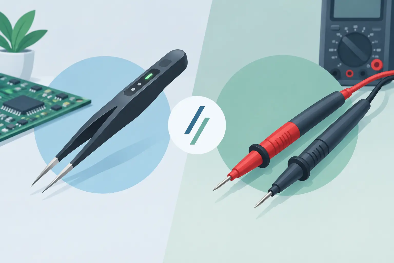
A 0402 capacitor with no visible marking is not a convenient place to use two loose probe tips. Neither is a crowded board where one slip can bridge adjacent pads. The smart tweezers vs probes decision comes down to more than tool preference: it determines how quickly you can isolate a component, how repeatable your readings are, and whether the instrument matches the physical constraints of the job.
For routine through-hole work, conventional probes remain useful and flexible. For identifying and checking discrete surface-mount components at the bench, integrated tweezer contacts can remove several steps from the measurement process. The right choice depends on component size, board access, required test conditions, and whether you are measuring a loose part or troubleshooting it in circuit.
Smart Tweezers vs Probes: The Core Difference
Smart tweezers combine an LCR meter and two closely spaced measurement contacts in one handheld instrument. When the tips touch a component, the instrument can identify whether it is measuring resistance, capacitance, or inductance, select suitable test conditions, and display the result. Many advanced models also provide ESR, diode testing, manual test-frequency selection, or Bluetooth data transfer.
Conventional probes are separate leads attached to a multimeter, LCR meter, oscilloscope, or other test instrument. They may be simple two-wire probes, grabber clips, needle probes, or Kelvin probe assemblies. Their strength is adaptability: users can reach distant test points, connect to large terminals, and work with measurement setups that require longer leads or specialized fixtures.
The distinction matters because contact geometry affects workflow. Tweezer tips are aligned for gripping a two-terminal chip component. Probes require the operator to position two independent contacts while watching spacing, pressure, and polarity where relevant. That difference may be minor on a 1/4-watt resistor and substantial on a dense PCB populated with 0201, 0402, or 0603 parts.
| Measurement consideration | Smart tweezers | Conventional probes | |—|—|—| | Contact placement | Two tips move as one unit | Each probe is positioned separately | | Best fit | Loose SMD parts and close-pitch board work | General-purpose testing and hard-to-reach nodes | | Setup time | Minimal for automatic component checks | Depends on meter mode, leads, and test setup | | Repeatability | High when tips land on the same terminations | More dependent on operator placement | | Physical reach | Limited by tip size and body access | Can be extended with leads, clips, and adapters | | Advanced setups | Limited to instrument capabilities | Supports fixtures, remote leads, and specialized probing |
Where Smart Tweezers Save Time
The primary advantage is direct, controlled contact. A technician can pick up a loose chip resistor, capacitor, or inductor and obtain a reading without selecting resistance, capacitance, or inductance first. This is valuable during incoming inspection, component sorting, rework, and board-level troubleshooting, where the question is often simple: what is this part, and is its measured value plausible?
Automatic mode selection also reduces avoidable errors. With separate probes and a traditional meter, an incorrect range or mode can produce an overload indication, an unstable reading, or a result that appears valid but does not answer the real question. A dedicated LCR tweezer instrument is designed around discrete-component measurement, so its workflow begins with contact rather than menu navigation.
Tip geometry is equally important. Fine tweezer tips give technicians a clear way to contact opposite terminations without holding two probes at an awkward angle. The hand position is more stable, and the risk of touching neighboring pads is reduced. For production rework and repair benches, that can mean faster checks with less interruption.
Devices such as LCR-Reader instruments are particularly practical when fast automatic measurement is the priority. The operator can verify a component before installation, compare it with a known-good part, or screen suspicious values on a board without moving to a benchtop meter for every basic check.
Where Probes Are the Better Tool
Probes are not obsolete because tweezers are faster on chip components. They solve different problems. If test points are several inches apart, buried under a cable, placed at opposite ends of a board, or located in a high-voltage section, leaded probes give the reach and separation that tweezer contacts cannot provide.
They are also better suited to measurements that depend on a larger test system. An oscilloscope probe captures waveforms, a current probe measures current without opening a circuit, and a four-wire Kelvin setup can reduce lead and contact resistance errors in low-resistance measurements. Smart tweezers provide efficient two-terminal component measurements, but they do not replace every probe type on an electronics bench.
Large components can favor probes as well. A radial electrolytic capacitor, power resistor, transformer winding, connector pin, or battery terminal may be physically too large or inconvenient for tweezer tips. Clip leads or standard probes provide a more secure connection, especially when the part must remain connected for an extended measurement.
Accuracy Depends on the Measurement Method
Neither format is automatically more accurate in every situation. Accuracy begins with the instrument specification, calibration status, selected test frequency, and measurement range. Contact quality then determines whether that capability reaches the device under test.
For small discrete SMD components, short integrated contacts can reduce the lead effects and handling variability associated with loose probe leads. This supports stable readings, especially when comparing components or checking low-value resistors. However, oxidation, flux residue, worn tips, and poor pressure can still create contact resistance or intermittent readings. Clean, undamaged tips and regular calibration checks remain essential.
For very low resistance, high accuracy often requires Kelvin measurement. In a Kelvin configuration, separate force and sense paths reduce the influence of lead resistance and contact resistance. A compatible Kelvin probe connector or fixture may therefore be the correct choice when milliohm-level work matters more than speed.
Capacitance and inductance measurements have their own limitations. Test frequency, component construction, parasitic effects, and circuit connections can shift the observed value. A reading from an in-circuit component should be treated as evidence, not automatic proof of failure. Parallel paths, semiconductor junctions, and nearby components can influence the result.
In-Circuit Testing Requires Judgment
Smart tweezers make in-circuit checks more convenient, but convenience does not eliminate circuit behavior. A resistor may read lower than its nominal value because another resistance path is in parallel. A capacitor may appear higher because it is connected to additional capacitance. An inductor reading may be affected by nearby circuitry or the DC resistance of the winding.
Use the reading as part of a troubleshooting sequence. Compare the suspect location with an equivalent channel, a known-good board, or the expected circuit value. If the measurement is inconsistent with the design and no parallel path explains it, lift one terminal or remove the component for confirmation.
Power must be removed before using an LCR or ESR measurement instrument unless the instrument documentation specifically permits the test condition. Discharge capacitors first. This protects the meter and prevents stored energy from producing a misleading or unsafe result.
Choosing the Right Tool for Your Work
Choose smart tweezers when your work centers on SMD identification, value verification, ESR checks, rework inspection, and fast troubleshooting on compact assemblies. They are most effective when components have accessible two-terminal pads and measurement speed matters throughout the day.
Choose probes when access, distance, voltage rating, waveform analysis, or specialized measurement topology is the deciding factor. They are the practical option for connector testing, power electronics, large components, remote nodes, and any task requiring a fixture or separate sense leads.
Many professional benches need both. Smart tweezers handle the rapid component-level decision: is this part the expected value, and does it behave like the surrounding components? Probes handle the wider circuit-level question: what is happening at this node, across this connector, or through this power path?
The productive choice is not to force one tool into every measurement. Keep the contact method as close as possible to the component and the question in front of you. When a small SMD part needs a quick, repeatable answer, tweezers reduce friction. When the circuit demands reach, isolation, or a specialized setup, probes provide the control needed to measure with confidence.