
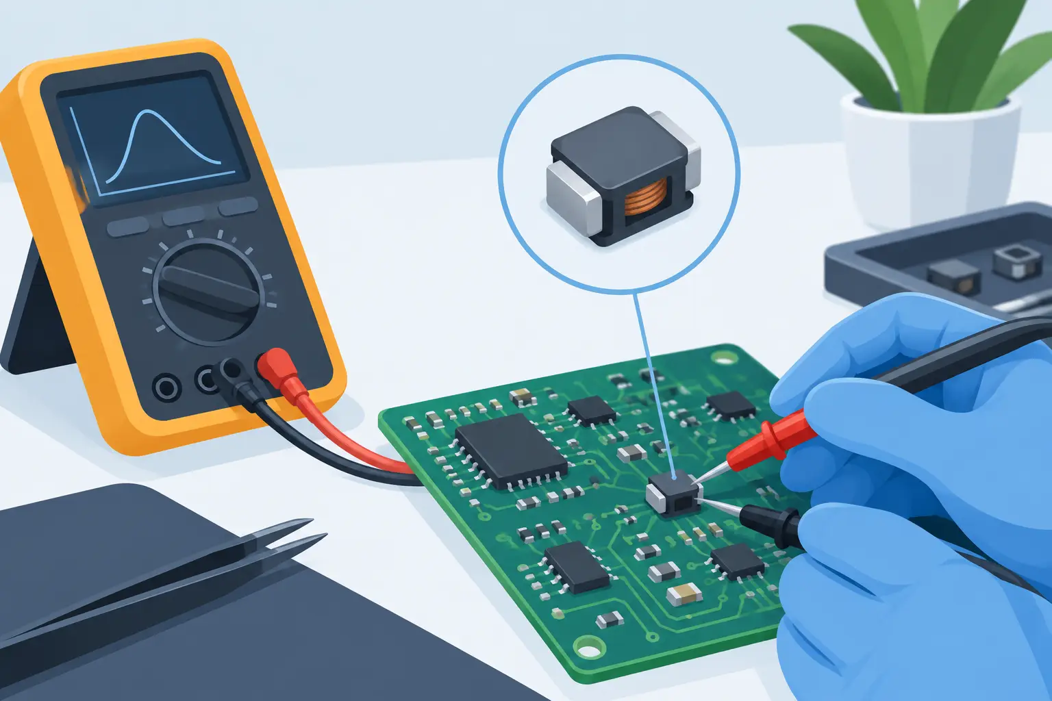
A 1 uH chip inductor can look perfect after rework and still be the reason a switching regulator will not start. That is why SMD inductance measurement is more than reading a nominal value from a meter. It is a controlled check of inductance, loss, contact quality, test frequency, and the surrounding circuit.
For PCB repair, incoming inspection, and SMT troubleshooting, the practical question is usually not whether an inductor is exactly on its printed or specified nominal value. The question is whether it behaves like a healthy component under conditions that make the reading meaningful. Small inductors have low resistance, small terminals, and frequency-dependent characteristics. A poor method can produce a plausible number that leads to the wrong diagnosis.
What an SMD Inductance Measurement Actually Shows
Inductance is the component’s opposition to changes in current. In a real surface-mount inductor, that behavior is affected by winding construction, magnetic core material, DC bias, AC test level, temperature, and frequency. The value displayed by an LCR meter is therefore a measurement at a particular test condition, not a universal property that remains unchanged in every circuit.
This matters most with low-value chip inductors and ferrite power inductors. A 100 nH RF inductor may require a high enough test frequency to obtain a stable, useful result. A power inductor used in a buck converter may measure near its nominal inductance at a small AC test signal, while its effective inductance falls substantially under operating DC current because the core approaches saturation.
A useful measurement also includes loss. Depending on the instrument and selected display mode, loss may be expressed as resistance, dissipation factor, or quality factor. DC resistance, commonly called DCR, is especially useful for power inductors. An open winding is easy to identify, but elevated DCR can indicate heat damage, a cracked termination, or an incorrect substitute part.
The nominal tolerance should guide the initial judgment. Many chip inductors are specified at ±20%, while tighter RF components may be ±5% or better. A reading outside the published tolerance is a concern only after the test frequency, fixture compensation, and circuit conditions have been checked.
Why Test Frequency Changes the Result
Inductors are not ideal. Their windings have resistance, their terminals add parasitic inductance, and their distributed capacitance eventually produces self-resonance. Below self-resonant frequency, the part generally behaves inductively. Near resonance, readings can become unstable or shift quickly. Above it, the component may appear capacitive.
For this reason, compare a measured result with the manufacturer’s specification at the same or a reasonably close test frequency. Measuring a 10 uH power inductor at 100 kHz when its datasheet specifies inductance at 1 kHz can yield a different result without proving that the component is defective. Conversely, a high-frequency RF inductor measured too slowly may be close to the lower resolution limit of the instrument.
The right frequency depends on the component and the purpose of the test. Use the datasheet condition when verifying stock or qualifying a replacement. When troubleshooting a board, use a frequency that gives stable readings and then compare identical components measured under the same conditions. Relative comparison is often faster and more defensible than trying to infer every parameter from a single in-circuit reading.
In-Circuit Measurement: Useful but Limited
In-circuit SMD inductance measurement can quickly reveal an open part, a shorted rail, or a major difference between matching power stages. It also has limits. An inductor connected to a regulator IC, capacitor bank, diode, transformer winding, or parallel filter path is no longer being measured alone. The meter sees the impedance of the full network.
A low reading across an inductor installed in a buck converter does not automatically mean the inductor is shorted. Its normal DCR may be only a few milliohms, and other paths in the circuit can dominate the result. Likewise, a capacitor in parallel can cause an LCR meter to identify the network as capacitive at its chosen test frequency.
Use in-circuit readings as a screening tool when the topology is understood. Compare the suspect point with a known-good board, a duplicate channel, or an equivalent stage on the same assembly. If the result is ambiguous, lift one termination or remove the component. Isolating just one end usually eliminates most parallel paths while minimizing rework risk.
Do not measure a powered board. Stored energy in nearby capacitors can also affect the reading or damage sensitive test equipment, so discharge the circuit and verify that the rail is at a safe voltage before contacting the part.
Contact Quality Is Part of the Measurement
The smallest SMD inductors are easy to probe badly. Standard pointed probes can slip, bridge adjacent pads, or scrape the component. Their lead inductance and contact resistance also become significant when measuring low inductance or low resistance.
Tweezer-style contacts are well suited to chip components because they apply both measurement terminals directly across the part with controlled spacing. They reduce setup time and make it easier to test loose components, components on tape, and parts installed in accessible PCB locations. A handheld LCR-Reader automatically identifies inductive components and selects a suitable measurement mode, which is useful when sorting mixed SMD stock or tracing faults at the bench.
Even with good tools, inspect the contact points. Oxidized solder, flux residue, cracked end caps, and probe contamination can create unstable readings. Hold the probes still, avoid pressing hard enough to fracture a small ceramic-core part, and repeat the measurement after repositioning. A healthy component should generally provide repeatable results when contact is sound.
For low-value inductors, compensate the fixture or test leads according to the instrument procedure. Open and short calibration removes much of the fixture’s parasitic behavior. It cannot correct for a poor connection at the component, so calibration and careful contact must work together.
A Practical Measurement Workflow
Start by identifying the component’s role. An RF matching inductor, an EMI bead, and a 4.7 uH power inductor may look similar, but they should not be evaluated by the same expectations. Board markings, the schematic, a bill of materials, and comparison with adjacent channels can establish the likely value and function.
Next, inspect the package under magnification. Look for a missing end cap, cracked body, overheated solder joint, discoloration, or a lifted pad. Mechanical damage often provides a clearer failure clue than a borderline inductance value.
Measure the part with the circuit unpowered. If measuring out of circuit, use the specified test frequency where possible and record inductance with resistance or loss. If measuring in circuit, first determine whether parallel paths are likely. A stable reading that agrees with a matching channel may be sufficient. A reading that is inconsistent, capacitive, or far from expectation should be confirmed with one pad lifted.
Then check repeatability. Take several readings while lightly reseating the probes. A value that changes dramatically with probe position may point to contact trouble, damaged terminations, or the influence of the surrounding circuit. Finally, compare the result against the tolerance and test condition in the component specification, not just the nominal marking or a generic online value.
Common Misdiagnoses
The most common error is treating continuity as an inductance test. A power inductor can show near-zero resistance and still have the correct inductance. Conversely, it may show continuity while its core has been damaged or its inductance has changed enough to affect converter ripple and regulation.
Another error is confusing ferrite beads with ordinary inductors. Ferrite beads are often specified by impedance at a high frequency, such as 100 MHz, rather than by a tightly controlled inductance value. An LCR meter can still provide useful information, but a direct inductance comparison may not reflect the part’s intended suppression performance.
A third issue is ignoring DC bias. Bench LCR meters typically use a small AC stimulus and do not reproduce the current in a working switching converter. If a regulator fails only under load, verify the inductor’s saturation-current rating, temperature rise, and waveform in addition to its small-signal inductance. A part can pass a bench measurement yet be unsuitable for the application.
Finally, do not assume that a same-size replacement is equivalent. DCR, saturation current, shielded versus unshielded construction, self-resonant frequency, and tolerance can all affect circuit behavior. The measured inductance is one requirement, not the complete replacement specification.
Accurate SMD inductor checks come from matching the tool and test condition to the component’s job. When the reading is repeatable, the circuit is understood, and the comparison is made at the right frequency, a tiny two-terminal part stops being a guess and becomes a fast, defensible repair decision.