
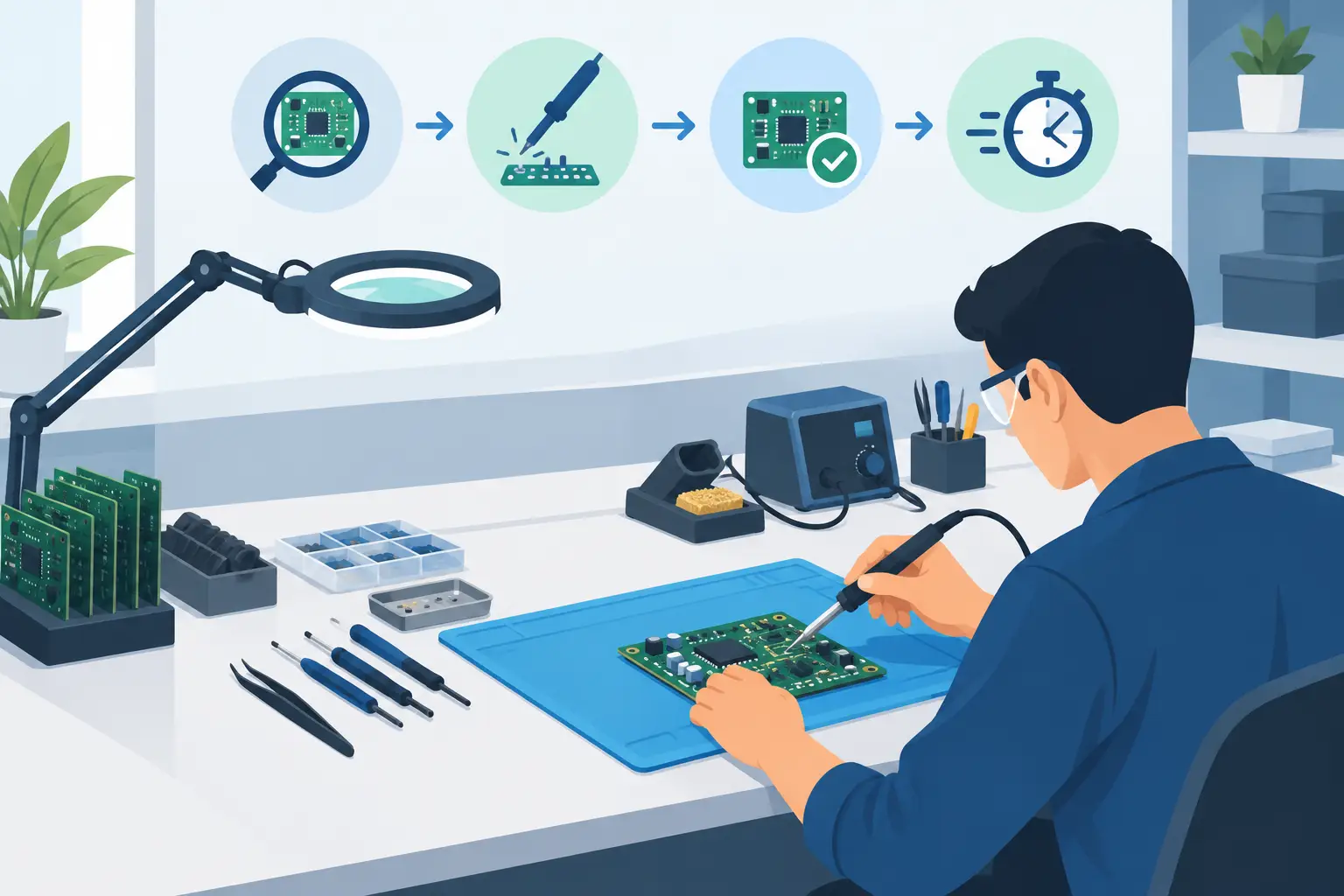
A failed board rarely arrives with a clean symptom. It may power briefly, draw too much current, fail only when warm, or appear completely dead. A disciplined pcb repair bench workflow example prevents the common mistake of replacing visible parts before identifying the actual fault path. The objective is not simply to find a bad component. It is to establish a repeatable sequence that protects the board, shortens diagnosis time, and produces a repair that can be verified.
For SMT work, workflow matters as much as instrument capability. Small capacitors, resistors, inductors, diodes, and IC support components are easy to disturb and difficult to identify once removed. Start with evidence, make low-risk measurements first, and apply power only when the board condition supports it.
Why Repair Benches Need a Defined Sequence
An organized bench separates observation from intervention. If a technician powers an unknown board immediately, a shorted rail can overheat an IC, damage a trace, or erase evidence that would have made localization straightforward. If components are removed before baseline measurements are recorded, the comparison data is gone.
The order below is designed for populated PCBs, including dense consumer, industrial, and embedded-control assemblies. It is not a rigid script. A board with corrosion requires cleaning and inspection before meaningful readings. A board with an obvious cracked connector may justify a focused mechanical repair. In most cases, however, the same progression reduces guesswork.
| Stage | Primary question | Useful output | | — | — | — | | Intake | What is the reported failure and board history? | Defined symptom and test target | | Unpowered inspection | Is there visible or measurable damage? | Suspect areas and rail baseline | | In-circuit checks | Which passive parts disagree with the circuit expectation? | Ranked component candidates | | Controlled power-up | Where does voltage, current, or temperature become abnormal? | Fault location or affected subsystem | | Verification | Does the repair hold under realistic conditions? | Documented pass result |
PCB Repair Bench Workflow Example: From Intake to Sign-Off
1. Record the board condition before touching it
Assign a job number and photograph both sides of the assembly. Record the board revision, serial number, reported symptom, power source, known history, and whether previous repair work is visible. This takes little time and avoids a familiar problem: a lifted pad, missing screw, or altered jumper later being mistaken for new damage.
Define a pass condition early. For example, a motor-control board may need to boot, communicate, and drive a load for 15 minutes. A power board may need specified output voltage at both no load and rated load. A repair is not complete because a short disappears. It is complete when the board performs its intended function within expected limits.
2. Make the board safe and inspect it unpowered
Disconnect all power sources, remove batteries where possible, and discharge high-voltage capacitors using an appropriate controlled method. Confirm that dangerous stored voltage is absent before probing. This is especially important in offline power supplies, inverter sections, and equipment with large bulk capacitors.
Inspect under magnification with angled lighting. Look for cracked MLCCs, darkened solder mask, solder bridges, corrosion around connectors, loose shield tabs, overheated inductors, and discolored vias. A cracked capacitor can look normal from above but show a fracture line at its termination. Also inspect the reverse side directly below hot components, where heat damage often appears first.
At this point, avoid assuming that discoloration identifies the failed part. A resistor may be dark because it is downstream of a short. An inductor may be warm because a regulator is operating outside its intended load range. Visual evidence establishes hypotheses; measurements decide which hypothesis survives.
3. Establish rail resistance and diode-mode baselines
With the board unpowered, identify the input rails and major local rails from markings, schematics, board layout, or known regulator sections. Measure resistance to ground and diode-mode readings in both probe directions where appropriate. Record the values rather than relying on memory.
Very low resistance is not automatically a defect. Modern processors, GPUs, FPGAs, and high-current digital rails can present low resistance by design. The useful comparison is between similar rails, known-good boards, expected circuit topology, and the behavior of the measurement as the probes settle. A direct short usually remains stable near zero ohms. A capacitive rail may climb as capacitors charge from the meter.
This is also the point to isolate external causes. Cables, daughterboards, displays, motors, and connected peripherals can create a misleading fault signature. Disconnect them methodically and repeat the baseline check after each change.
4. Measure suspect SMT passives in circuit
Once a suspect area is identified, check surrounding passive components before removing anything. An automatic tweezer-style LCR meter is particularly effective here because it can contact small SMD terminations directly and identify resistance, capacitance, inductance, and ESR without a lengthy test setup.
For example, compare several decoupling capacitors on the same rail. One capacitor that reads abnormally low resistance, has a markedly different capacitance value, or produces an inconsistent reading deserves closer investigation. Compare like with like: same package size, same rail, and preferably the same reference designator function. A 10 uF input capacitor and a 100 nF local bypass capacitor should not be expected to behave identically in circuit.
In-circuit measurement has limits. Parallel components can lower an apparent resistance or raise apparent capacitance. Semiconductor junctions and active IC paths may influence readings. When the value is critical and the surrounding network makes it ambiguous, lift one terminal or remove the part only after documenting the original condition. LCR-Reader instruments are useful for fast component screening, but no meter can override circuit topology.
5. Apply power with a current limit and a purpose
If the unpowered checks do not reveal a clear hard short, move to controlled energizing. Use a bench supply set to the board’s correct input voltage and begin with a conservative current limit. Watch the current response as power is applied. An immediate clamp at the limit suggests a short or heavy fault; a low, stable current may indicate an open path, missing enable signal, or startup-sequence failure.
Measure rails in sequence from input to downstream regulators. Verify enable pins, output voltages, ripple where relevant, and reset signals. Do not chase every node. Each measurement should test a specific question: Is the main input present? Did the buck regulator start? Is its output loaded down? Is the controller receiving its enable condition?
Thermal methods can help once current is safely limited. A thermal camera, freeze spray, or carefully applied IPA evaporation test may reveal a heating component. These methods are most reliable when paired with electrical evidence. A warm IC is not necessarily faulty, but a component that heats immediately on a low-voltage rail while the rest of the board remains cool is a strong lead.
6. Repair the cause, then inspect the workmanship
Before rework, confirm part specifications from markings, documentation, or a known-good board. Match the electrical value, voltage rating, tolerance, dielectric where relevant, package size, and thermal capability. A replacement capacitor with the right nominal capacitance but unsuitable voltage rating or DC-bias behavior can create a repeat failure.
Use controlled heat and appropriate flux. After replacement, inspect solder joints under magnification and check for bridges, incomplete wetting, tombstoned passives, displaced neighboring parts, and damaged pads. Clean flux residue when it could interfere with inspection, high-impedance circuitry, or conformal-coating repair.
7. Verify beyond the original symptom
Repeat the unpowered rail measurements first. A repaired short should produce a changed and explainable baseline. Then power the board under current limit, verify all relevant rails, and run the functional test defined at intake. If practical, allow the assembly to warm up and repeat the test under realistic load.
Document the failed component, measured evidence, replacement details, and final test results. This record improves future repairs, especially for recurring product faults. It also distinguishes a verified repair from a board that merely turned on once at the bench.
Build the Bench Around Fast, Repeatable Decisions
A productive repair bench does not require every instrument for every job. It requires reliable access to magnification, controlled power, voltage and continuity checks, component measurement, soldering and hot-air tools, and a method for recording findings. Keep probe tips clean, verify meter calibration status, and use fixtures or Kelvin connections when low-value measurements demand better contact control.
The practical value of this workflow is cumulative. Each stage narrows the fault without creating new variables, and each recorded reading makes the next repair faster. When the board finally returns to service, the best result is not a lucky component swap. It is a repair path clear enough that another technician can follow the evidence and reach the same decision.