
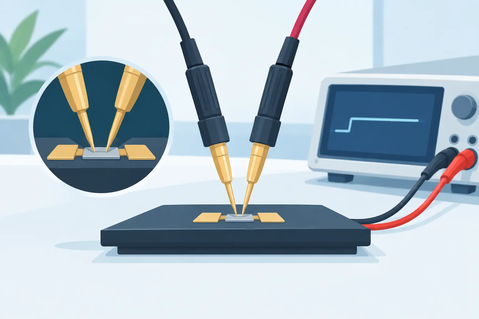
A resistance reading of 0.08 ohms can look straightforward until the test leads, probe contact, and oxide on a solder joint contribute as much resistance as the part under test. Kelvin probes address that problem by separating the current path from the voltage-sensing path. For repair work, SMT inspection, cable testing, and production verification, that separation can determine whether a measurement is useful or misleading.
Two-wire resistance measurement is adequate for many components. It is not automatically adequate for low-value resistors, battery contacts, shunts, relays, connectors, traces, or solder joints. As the resistance being measured approaches the resistance of the leads and contact points, ordinary probes become a significant source of error.
What Kelvin Probes Do Differently
Kelvin probes are used for four-wire resistance measurement, also called Kelvin measurement. A typical two-wire meter sends test current through its leads and measures voltage through those same leads. The displayed result includes the resistance of the test leads, probe tips, connections, and the device under test.
A four-wire arrangement assigns two conductors to force a known test current through the component. The other two conductors sense voltage directly at the measurement point. Because the voltage-sensing inputs draw extremely little current, their lead resistance creates negligible voltage drop. The instrument can therefore calculate the resistance of the component from the voltage measured at its terminals and the current applied through the force leads.
The principle is simple:
Resistance = measured voltage / applied current
What changes is where the voltage is measured. Kelvin connections place the sensing points as close as practical to the device terminals. That keeps lead and contact losses out of the primary result.
Why Two-Wire Measurements Can Mislead
Consider a 10 milliohm connection measured with standard probes. If the combined resistance of both leads and their contact points is 60 milliohms, the meter may display a value closer to 70 milliohms. Even if lead compensation is available, the result can shift when probe pressure, position, surface condition, or contact geometry changes.
Zeroing or relative mode helps compensate for stable lead resistance, but it does not solve every problem. It cannot fully remove variable contact resistance at the part, especially when testing oxidized terminals, uneven solder joints, plated pads, or high-current connectors. Kelvin probing reduces this sensitivity because the voltage is sensed at the component rather than inferred through the current-carrying leads.
This distinction matters most when the expected value is very low. A few milliohms may be insignificant when checking a 10-kilohm resistor. The same few milliohms can be the difference between a good and failing crimp, a sound and cracked solder joint, or a properly installed and damaged current shunt.
Where Kelvin Probes Are Most Useful
Kelvin measurement is not reserved for laboratory resistance standards. It is practical wherever low resistance needs to be measured with repeatable contact placement.
Low-Value Resistors and Current Shunts
Shunt resistors are commonly specified in milliohms and used for current sensing in power supplies, battery management circuits, motor controllers, and instrumentation. Measuring them with ordinary probes often produces a reading dominated by the probes rather than the shunt. Kelvin contacts applied directly at the resistor terminations provide a more meaningful result.
For four-terminal shunts, use the dedicated sense terminals where available. For two-terminal parts, place the current contacts toward the outside of each terminal and the voltage-sense contacts closer to the resistor body. This arrangement minimizes the influence of terminal and solder resistance.
PCB Traces, Vias, and Solder Joints
A board trace or solder joint may have resistance too low for a conventional handheld meter to characterize reliably. Kelvin probes can help compare like points across a production board, locate a high-resistance path, or verify a repair after rework.
Results still require judgment. A short, wide copper trace may measure only a few milliohms, and the measured value will vary with trace length, copper weight, temperature, and contact location. The most useful practice is often comparison: measure a known-good board using the same probe placement, then compare the suspect board under identical conditions.
Connectors, Switches, Relays, and Cable Assemblies
Contact resistance increases with contamination, wear, weak spring pressure, corrosion, and poor crimp quality. A four-wire test can expose resistance that a continuity buzzer will not reveal. Continuity indicates that a path exists. It does not prove that the path is suitable for current delivery.
For connectors and relay contacts, use a test current appropriate for the device and the instrument. Very low current may not break through oxide films, while excessive current can heat or damage sensitive contacts. The required method depends on the component specification and the failure mode being investigated.
Probe Contact Is Still Part of the Measurement
Kelvin probes reduce lead error, not every source of error. Poor technique can still produce unstable or incorrect results. The force and sense connections must contact the intended points, and the contact geometry must remain consistent between measurements.
Clean terminals before testing whenever practical. Flux residue, oxidation, conformal coating, and surface contamination can raise contact resistance or make readings intermittent. Sharp, well-maintained probe tips improve repeatability on pads and terminals, but excessive pressure can damage fine-pitch assemblies or slip across adjacent conductors.
For small surface-mount components, tweezer-style instruments and Kelvin probe adapters can make placement more controlled than loose bench leads. The best arrangement depends on package size, board access, and whether the component is measured in circuit or removed from the board. In-circuit readings can be affected by parallel paths, semiconductor junctions, and charged capacitors, even when the probe connection itself is correct.
Choosing the Right Kelvin Probe Configuration
The right probe is determined by the work, not just the lowest resistance on the datasheet. Fine-point Kelvin probes are useful for SMT pads, narrow traces, and compact assemblies. Larger clips or clamps are better suited to battery tabs, cable lugs, bus bars, and relay terminals. Some test setups use separate force and sense clips, while others combine all four contacts in a single probe body.
When selecting a Kelvin accessory, verify connector compatibility with the instrument, supported measurement range, acceptable test current, lead length, and insulation rating. Longer leads are convenient but can be more susceptible to noise and harder to position consistently. Shielding and guarding may also matter in sensitive low-level measurements, particularly when working around switching power circuits.
Calibration is equally relevant. A capable instrument cannot compensate for damaged cables, worn probe tips, loose connectors, or an unverified measurement setup. Inspect the probe regularly, keep contacts clean, and use the manufacturer’s recommended calibration or verification procedure. For production or quality-control work, documented checks against known low-resistance standards help maintain confidence in results.
A Practical Measurement Workflow
Start by confirming that the circuit is de-energized and that stored energy has been discharged. Identify the expected resistance and decide whether lead resistance could materially affect the result. If the expected value is in the milliohm range, a Kelvin method is usually the correct starting point.
Place the force contacts so current flows through the entire section being evaluated. Place the sense contacts inside those force contacts, as close as possible to the component body or actual connection under test. Allow the reading to settle, then repeat the measurement with the same placement. A stable result across repeated checks is more useful than a single optimistic number.
If the value is unexpected, do not immediately assume the component has failed. Check for parallel circuit paths, thermal effects, contamination, probe movement, and differences in test current. Comparing against a known-good assembly often resolves uncertainty faster than relying on a nominal value alone.
LCR-Reader instruments and compatible Kelvin probe connectors are particularly useful when compact component access and controlled measurement technique matter at the bench. The goal is not simply to obtain more digits on a display. It is to obtain a reading that represents the device, joint, or path you intended to test.
A Kelvin measurement is most valuable when it becomes part of a repeatable process: clean contact points, consistent probe placement, appropriate test current, verified accessories, and comparison against known-good results. That discipline turns milliohm readings into evidence technicians can act on.