
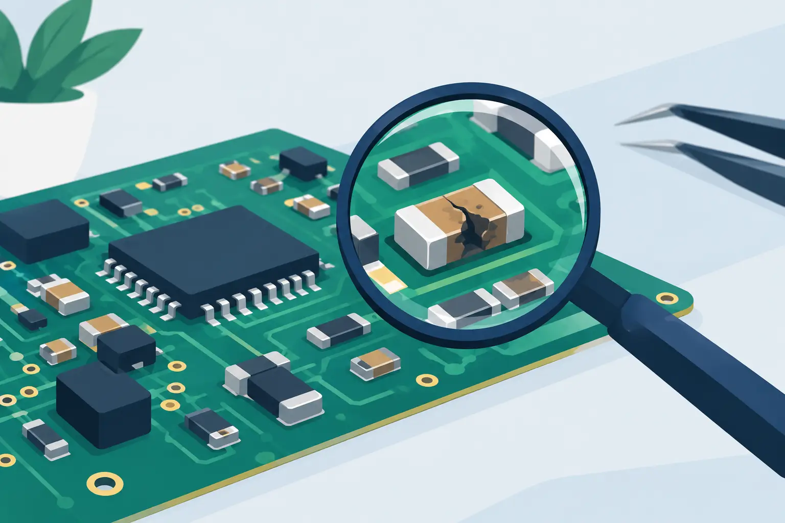
A board can look immaculate and still fail because of one cracked 0402 capacitor, a resistor that drifted under load, or an inductor with a damaged winding. Finding damaged passive components requires more than spotting burn marks. It requires a repeatable process that combines board history, visual evidence, circuit context, and measurements taken with the right test conditions.
For technicians working on dense SMT assemblies, the objective is not simply to find a part with an unusual reading. The objective is to determine whether that reading is caused by the component itself, a parallel path in the circuit, a semiconductor fault nearby, or the way the board is being tested.
Start With the Failure, Not the Component
A passive component does not fail in isolation. Begin with the reported symptom: no power, unstable output voltage, excessive ripple, intermittent operation, a shorted supply rail, poor RF performance, or a missing signal. That symptom narrows the part of the circuit that deserves attention.
For example, a board that resets when a motor starts may have a degraded bulk capacitor, a cracked ceramic capacitor near a regulator, a high-resistance current-sense resistor, or a damaged connection. A rail that reads near zero ohms to ground may point to a shorted MLCC, but it may also be caused by an IC on the same rail. Measurements only become meaningful when they are connected to the schematic function of the section being tested.
Before probing, confirm the board is unpowered and that energy-storage capacitors have been safely discharged. Remove batteries and external supplies. Do not use resistance or LCR functions on a live circuit. A meter can be damaged, and the resulting measurement can be misleading.
Visual Inspection Still Finds Real Faults
Magnification and good lighting remain useful because physical damage often provides the fastest answer. Look closely around power devices, connectors, inductors, high-current paths, and areas exposed to mechanical stress.
Cracked MLCC capacitors are particularly common near board mounting holes, heavy connectors, shield edges, and locations where the PCB flexes. Their cracks may be difficult to see from above and can appear only after removing conformal coating or viewing the component from an angle. A cracked capacitor may become intermittently shorted as the board bends or heats.
Also inspect for discolored resistors, lifted terminations, tombstoned parts, corroded pads, solder bridges, and inductors with damaged cores or overheated insulation. A darkened resistor is not automatically defective, but it is evidence that the circuit experienced excess power dissipation. Verify its measured value and determine why it was stressed before replacing it.
Finding Damaged Passive Components With Measurements
A multimeter is valuable for basic continuity, resistance, and gross short-circuit checks. It is often not enough for diagnosing small passives on populated boards. Resistance alone cannot identify capacitance, inductance, ESR, dielectric loss, or a capacitor that changes behavior at a relevant test frequency.
A handheld LCR meter with tweezer probes is well suited to component-level work because it can contact small SMD terminations directly. Automatic component identification reduces setup time when moving between resistors, capacitors, and inductors during a fault search. Tools such as LCR-Reader meters are designed for this workflow: touch the terminals, obtain a measured value, and compare it with the expected value or a known-good board.
The comparison matters more than a single number. A 10 kOhm resistor that measures 9.96 kOhm is generally behaving as expected. A 10 kOhm resistor measuring 47 kOhm, open circuit, or a value that shifts when gently pressed is a strong fault candidate. For capacitors and inductors, compare not only nominal value but also ESR, dissipation factor where available, and consistency across identical circuit locations.
Measure Resistors for Drift and Open Connections
Resistors commonly fail open, drift upward in value, or develop intermittent termination faults. Low-value resistors used for current sensing, fusing, or power distribution deserve special attention. Their values can be so low that probe and contact resistance affect the result.
Use clean probe tips and firm contact on the component terminations. For very low resistance measurements, Kelvin methods reduce errors caused by leads and contact resistance. If a resistor is in parallel with another circuit path, its in-circuit value may read lower than its marked or nominal value. Lifting one end may be necessary when a precise diagnosis is required.
Do not overlook resistor networks. A single open element in an array can disable a pull-up, feedback divider, address strap, or termination network while the rest of the package appears normal.
Check Capacitors for Shorts, Loss, and ESR Changes
Ceramic capacitors frequently fail shorted, especially on low-voltage power rails. Start with a resistance or continuity check from the rail to ground, then isolate the section through ferrite beads, jumpers, or inductors if the schematic permits. Measure capacitors within the suspect section and compare similar decoupling locations.
A low resistance reading across a capacitor does not prove that the capacitor is shorted. Other components on the same rail can dominate the measurement. In that case, remove the capacitor only after comparing evidence from several locations or after isolating branches of the supply network.
Aluminum electrolytic and polymer capacitors often show aging through increased ESR, reduced capacitance, leakage, or poor performance under ripple current. A capacitance value close to nominal does not guarantee a healthy part. Elevated ESR can cause unstable regulators, excessive output ripple, poor startup behavior, and load-dependent resets. ESR measurement is therefore particularly useful on power input and output capacitors.
MLCC values also depend on applied DC bias, temperature, and test frequency. A reading that differs from the printed value is not automatically a failure. Compare it with the same part under similar conditions, or use the manufacturer’s data when available.
Test Inductors in Their Circuit Role
Inductors can fail open, change inductance, develop high DC resistance, or suffer damaged cores after overheating. In switching regulators, inspect the inductor together with the MOSFETs, diode or synchronous rectifier, controller, and output capacitors. Replacing only the visibly stressed inductor can lead to a repeat failure if the actual cause is a shorted switching device or overload downstream.
Measure inductance and DC resistance when the circuit allows it. A reading near zero ohms may be normal for a power inductor, so compare against a known-good assembly or the specified DCR. An open inductor is usually clear, while partial saturation or core damage may only appear during powered operation under load. That is an example where a static bench measurement has limits.
Know When In-Circuit Readings Are Trustworthy
In-circuit testing is fast, but it is not magic. Parallel components can lower a resistance or raise apparent capacitance. Semiconductor junctions can influence readings. A regulator feedback network can make a resistor look incorrect even when the resistor itself is within tolerance.
Use a measured value as strong evidence when it is dramatically different from expectation, when identical nearby components provide a comparison, or when the circuit path is simple. Treat it as a clue rather than a verdict when the component is connected to a complex IC, a low-impedance rail, or several parallel paths.
When the result is uncertain, isolate one terminal and remeasure. This adds rework risk and time, so it should be done deliberately. On multilayer boards with small pads, an unnecessary lift can create more damage than the original fault.
Use Comparison as a Diagnostic Instrument
The fastest fault-finding resource is often a known-good board. Measure corresponding components in the same power domain, feedback loop, filter stage, or signal channel. This approach accounts for the designer’s actual component selection and the real behavior of the populated circuit.
If no reference board is available, use the schematic, board markings, component package codes, and design logic. A 1 uF bypass capacitor near an IC should not normally measure as a dead short when the local rail is isolated. A feedback resistor divider should preserve its expected ratio. A ferrite bead should have continuity at DC, while a fuse should not show a significant voltage drop under its rated operating condition.
Add Heat and Mechanical Stress Carefully
Intermittent faults often need controlled stimulation. Gentle board flexing, localized heating, or cooling can expose cracked capacitors, fractured solder joints, and resistors with unstable terminations. Use insulated tools, ESD-safe handling, and small temperature changes. Excessive force or uncontrolled heat can turn a marginal board into a permanently damaged one.
Thermal behavior should be verified with measurements before and after the stimulus. If a capacitor changes from a short to a normal reading after cooling, record the location and isolate it for confirmation. If a resistor’s value changes significantly with modest heat, evaluate whether its tolerance and temperature coefficient explain the change before condemning it.
A disciplined record of readings, board locations, and operating conditions prevents repeated work and makes the repair defensible. The best next measurement is rarely the broadest one. It is the one that tests the specific electrical reason a component is suspected.