
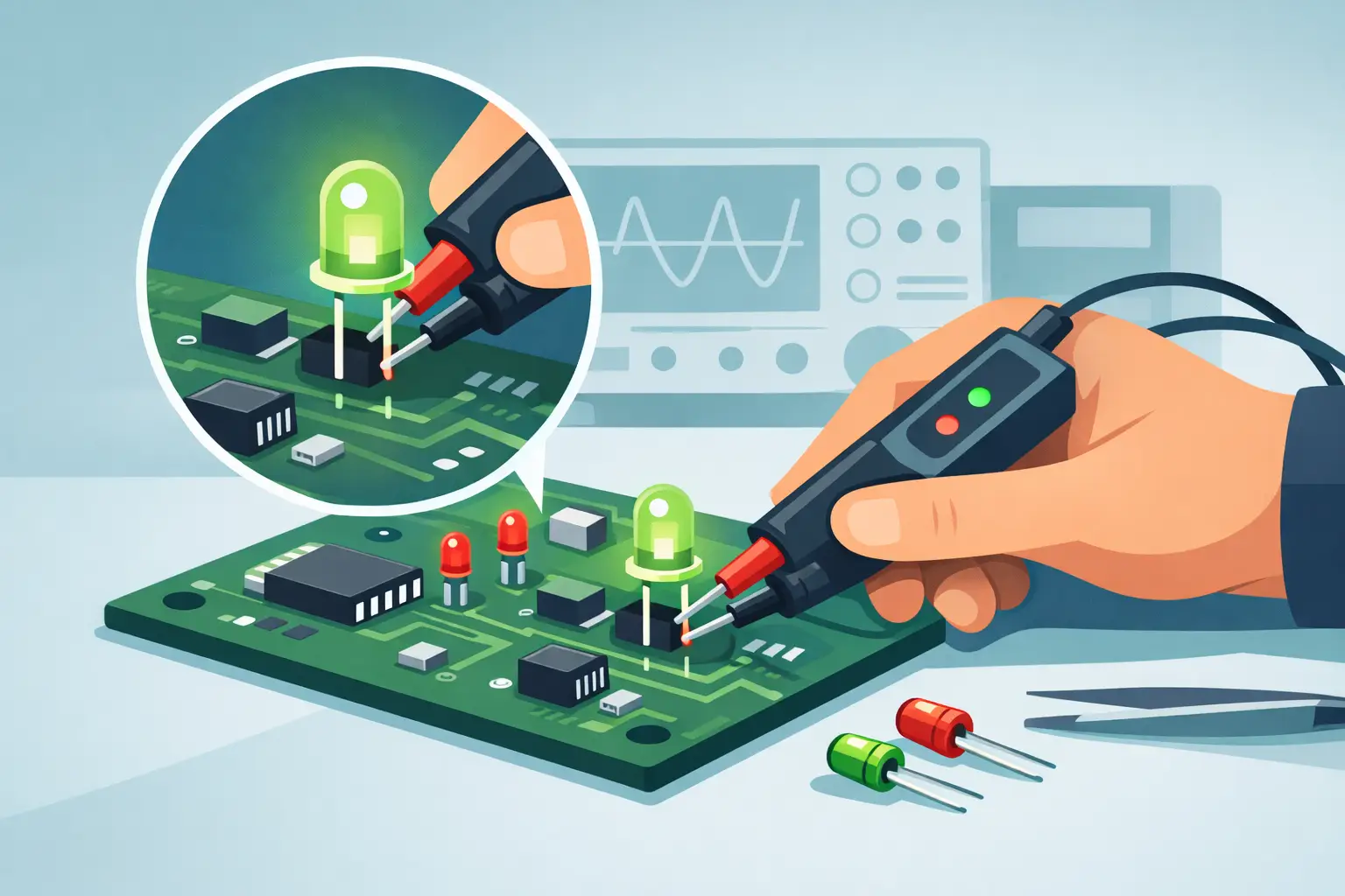
A reversed LED can look exactly like a failed LED during a rushed repair. On a densely populated board, the package marking may be obscured, the silkscreen may be incomplete, and a standard continuity test may provide no useful answer. An LED polarity tester applies a controlled test current to identify the anode and cathode while confirming whether the LED illuminates.
For technicians working with surface-mount LEDs, this is more than a convenience. Correct polarity identification prevents unnecessary rework, reduces the chance of installing replacement LEDs backward, and helps separate a damaged LED from a fault elsewhere in the circuit. The best method depends on whether the LED is loose, mounted on a board, or part of a larger backlight or high-power assembly.
What an LED Polarity Tester Actually Checks
An LED is a diode. It conducts current primarily in one direction: from anode to cathode. When forward biased with adequate voltage and properly limited current, it emits light. When the test leads are reversed, the LED normally blocks current and remains dark.
An LED polarity tester uses this behavior to establish orientation. A positive test probe is placed on one LED terminal and a negative probe on the other. If the LED lights, the positive probe is contacting the anode and the negative probe is contacting the cathode. If it does not light, the probes may be reversed, the applied test voltage may be insufficient, the LED may be defective, or the surrounding circuit may be influencing the result.
That last condition matters. A simple illuminated or not illuminated result is useful, but it is not always a complete diagnosis. White, blue, ultraviolet, and series-connected LEDs often require a higher forward voltage than red, green, or infrared devices. A tester with insufficient compliance voltage may report no illumination from a functioning device. Conversely, a dim glow can be a valid result when a tester intentionally uses low current to protect small indicator LEDs.
Why Polarity Is Easy to Misidentify
Through-hole LEDs usually provide visible orientation clues. The longer lead is commonly the anode, while the flat side of the lens identifies the cathode. Those conventions are helpful, but they disappear after leads are trimmed or when the LED has been removed from an assembly.
SMD LEDs create more uncertainty. A package may use a dot, notch, beveled corner, colored mark, or bottom-side pad geometry to identify cathode orientation. Marking conventions vary by manufacturer and package family. A 0603 LED can be too small to inspect reliably without magnification, while larger side-emitting and reverse-mount packages may use orientation marks that are not visible after assembly.
Board markings are not a guaranteed answer either. The diode symbol on a PCB may be missing, covered by conformal coating, or oriented in a way that is difficult to trace around nearby components. A direct electrical test removes guesswork, provided the test tool is appropriate for the LED and test condition.
Selecting the Right Test Method
A multimeter diode mode is often the first tool available. It can identify polarity on many low-current LEDs by applying a small test current and displaying forward voltage. If the meter drives the LED enough to produce a faint glow, polarity is immediately visible. However, many handheld meters do not provide enough test voltage for white or blue LEDs, and their probe tips can be awkward on fine-pitch pads.
An LED polarity tester is purpose-built for this task. It should provide controlled current, sufficient voltage for the target LED types, and probes or contacts sized for the work. For small SMD parts, tweezer-style contacts are especially effective because both terminals can be contacted at the same time without holding two separate probes steady.
For board-level work, consider three practical questions:
- Is the LED tested in circuit or out of circuit?
- What forward voltage is expected for its color, construction, or series arrangement?
- Can the test current damage the LED, its driver IC, or parallel components?
- Does the package require pointed probes, clips, or precision tweezers?
A low-current tester is usually preferred for indicator LEDs and unknown SMD parts. Higher-current capability can be useful for larger LEDs and strips, but it must be used deliberately. More current does not automatically produce a better diagnostic result.
Testing a Loose LED Safely
Start by inspecting the package. Look for a cathode mark, PCB symbol, lens flat, or datasheet reference if the part is identified. Visual inspection gives a useful cross-check, but do not rely on it alone when the device has uncertain markings.
Place the tester contacts across the LED terminals with correct spacing and light pressure. Apply the test using the lowest suitable current. When the LED illuminates, record the probe orientation: the positive contact is on the anode and the negative contact is on the cathode. If the tester displays forward voltage, record that value as well. It can help identify mismatched replacement parts later.
If there is no light, reverse the contacts once. A good LED should illuminate in one orientation only. No illumination in either direction may indicate an open LED, inadequate tester voltage, poor contact, or an LED designed for a voltage beyond the tester’s capability. Do not keep increasing test energy without confirming the LED’s expected electrical requirements.
A very low forward-voltage reading in both directions can indicate a shorted device. This is less common than an open failure in indicator LEDs, but it can occur after electrical overstress or physical damage. A polarity test should be followed by appropriate circuit checks when the result is ambiguous.
In-Circuit LED Testing Requires Judgment
Testing an LED while it remains soldered to a board saves time, especially during SMT troubleshooting. It also introduces parallel paths. Driver transistors, ESD protection networks, adjacent LEDs, capacitors, and pull-up resistors may affect the observed reading or allow current to bypass the target LED.
Before testing, make sure the board is unpowered and stored charge has been discharged. Never use an LED tester on a live circuit unless the instrument and procedure explicitly support that application. A powered driver can produce misleading results and may expose the tester to damaging voltage.
Contact only the LED pads when possible. If the LED lights in one direction, its polarity is established. If it does not, compare the result with an identical LED elsewhere on the board. This comparison is often more useful than interpreting one isolated reading. Two matching LEDs tested under the same conditions should show similar behavior unless one is faulty or connected differently in the circuit.
When parallel circuitry prevents a clear result, lift one LED terminal or remove the device for an out-of-circuit test. This adds rework time, but it is preferable to replacing a functioning component based on an unreliable in-circuit reading.
Interpreting Brightness and Forward Voltage
Brightness during a test is not a calibrated measurement of LED quality. It depends on test current, human vision, lens type, ambient light, and the LED’s efficiency. A dim LED may be completely functional if the tester uses microamp or milliamp-level current. A bright LED may still be unsuitable for the circuit if its forward voltage, color bin, or current rating differs from the original part.
Forward voltage is more informative, but only when compared under similar current conditions. Typical red LEDs may operate near 1.8 V to 2.2 V, while many white and blue LEDs operate closer to 2.8 V to 3.4 V. These are broad working ranges, not identification rules. High-brightness LEDs, infrared emitters, multichip packages, and series assemblies can differ substantially.
For replacement verification, compare the suspect LED to a known-good matching LED with the same tester and test setting. A significant difference in illumination or forward voltage may justify further inspection. It does not, by itself, prove the component has failed.
Why Tweezer-Style Testing Improves SMT Workflow
Separate probe leads work well for larger components, but they are inefficient on 0402, 0603, and similar LED packages. One probe can slip while the other is being positioned, causing intermittent contact and inconsistent results. Fine probes also increase the risk of bridging adjacent pads.
Tweezer-style LED test instruments place both contacts in one hand. The operator can align the tips with the LED terminals, apply consistent contact pressure, and observe illumination without managing two loose leads. This format is particularly useful during incoming inspection, prototype assembly, rework verification, and board repair.
LCR-Reader LED Test Tweezers are intended for this type of contact-sensitive work, where controlled LED testing and direct polarity confirmation can reduce time spent interpreting package marks. For technicians already using precision tweezers to measure SMD passives, the workflow is familiar: isolate the target pads, make stable contact, and evaluate the result in context.
Avoid These Common Testing Errors
The most frequent error is treating every dark LED as failed. First verify lead orientation, contact quality, tester voltage, and whether the device is part of a series string. A second common error is testing with excessive current. Small SMD indicators can be damaged quickly if a high-power supply or improvised battery test is used without current limiting.
Also avoid using polarity results as a substitute for circuit analysis. A correctly oriented, functional LED will not illuminate in its finished product if the driver output is missing, the current-limiting resistor is open, the control signal is absent, or the supply rail has failed. Polarity testing identifies the LED’s directional behavior. It does not validate the complete circuit.
A reliable LED test is a short, controlled measurement with a clear purpose: identify orientation, confirm basic conduction, and decide whether deeper diagnosis is necessary. That discipline keeps a simple polarity check from becoming another source of board damage or unnecessary rework.