While the device can be used with a variety of programs, LCR-MPA-BT Logger is the proprietary software for using LCR-Reader-MPA BT for PC. The program allows users to record measurements in real time, set custom profiles and save measurement data. The Logger’s main feature is the efficiency while testing; when testing components for specific tasks, users generally need to remember specific parameters a component must meet, this can get time consuming while testing many components. The Logger allows users to set a custom profile with the specific parameters the component must meet. While testing, the program will automatically determine while the component fits these parameters, granting a pass or fail automatically. The main display of the program will turn red when a component is failed, and is recorded as such in the list of values. Users can also set profiles for testing many components and various values for each component. All measurement data can be exported to Excel with just a press of the button. This is an exceptionally helpful ability, especially for quality control situations. The data can also be processed into databases or other forms depending on the task.
The picture above shows the program testing a single component; a custom profile has been set with the desired values. The main display of the device is showing red, which means the component under test does not meet the parameters specified. The list of previously measured components shows in the rows below the main display area; the rows marked with green are components that have been measured and fit the specified parameters.
The main display of LCR-MPA-BT Logger. This display shows the measurement value as displayed on the LCR-Reader-MPA – the main impedance value, secondary value, test mode, test frequency, signal level and series. Each of these are clickable; users can change the basic features from this screen by click them. A small menu will pop-up with options to choose from.
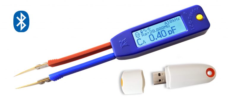
LCR-Reader-MPA BT is available with grey or black display from the LCR-Reader Store.