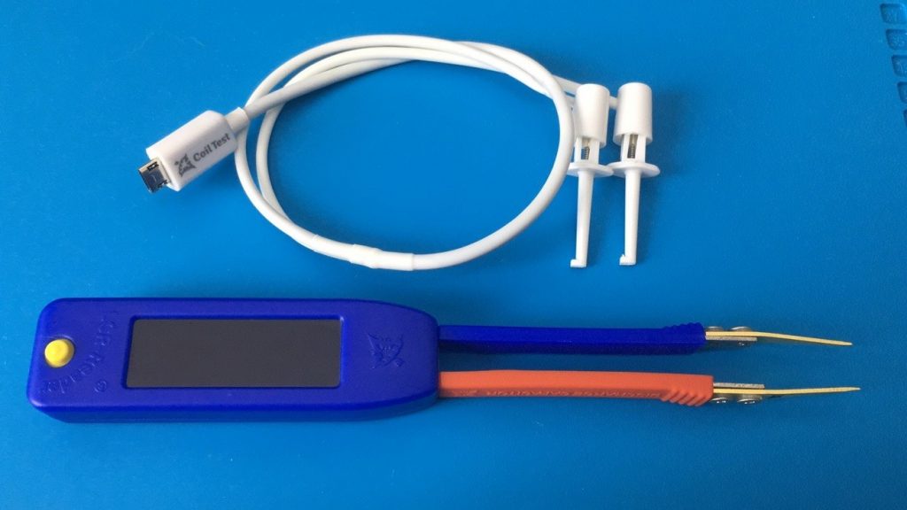
Siborg System Inc. has added a Ring Coil Tester to their line of testing equipment for use with the LCR-Reader line of multimeters.

Basic inductor or coil tests can be done using any LCR meter, like LCR-Readers. When testing, if the device shows any continuity or reading this shows that the coil winding is not destroyed. Often, the coil reading may show a slight deviation in values that is only detectable by knowing the exact original values of R or L. If there is one or a few turns of the winding that have short, the values would only show a slight variation.
Using the Ring Test method is a proven accurate method of finding short turns in a coil. This method has been used for repairing old-style audio-video equipment that employ flybacks, deflection yoke windings, motors, chopper transformers, main transformers, VCR video and other magnetic heads.
The Ring Test Method is based on the theory that if a faulty coil or transformer has shorted turn(s) in one of the coils, the Q-factor of the transformer is drastically redacted. when an impulse is applied, a faulty transformer will resonate with a highly damped oscillation while a good one will decay graduall.
When connected to a high quality capacitor across one winding of the investigated device and a pulse is applied to the parallel resonant circuit, the waveform across the resonant circuit will produce a decaying oscillation. It will do this for at least a few cycles if the coil is good. The oscillations will be strongly damped and only complete one or two cycles if there is a shorted turn in any of the magnetically coupled coils of the device. A short turn can also be applied, if possible, to compare the behavior with and without the short turn. If no change is detected, there must be a shortened turn in at least one coil.
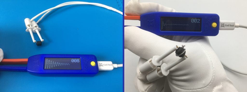
To use with LCR-Reader-MPA, connect the Ring Coil Tester using the micro-USB port on the device and connect a coil by the hook connectors. Set the MPA to “winding turns” in the menu. The display will show the excitation response from the coil. The figures below shows the difference between a good or bad coil. The shorted turn is connected and displays a significantly higher dissipation factor and therefore a fewer number of oscillations following the impulse on the coil.

